
F3726, F3211, F3174, R5135, R3816-HP Firewalls and UTM Devices Network Management Configuration Guide-6PW100


206
527BDisplaying and maintaining the DHCP client
Task Command
Remarks
Display specified
configuration information.
display dhcp client [ verbose ] [ interface
interface-type interface-number ] [ | { begin |
exclude | include } regular-expression ]
Available in any view.
528BDHCP client configuration example
1251BNetwork requirements
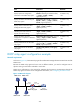
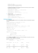
As shown in 2423HFigure 124, Firewall contacts the DHCP server through GigabitEthernet 0/1 to obtain an IP
address, DNS server address, and static route information. The DHCP client IP address resides on
network 10.1.1.0/24. The DNS server address is 20.1.1.1. The next hop of the static route to network
20.1.1.0/24 is 10.1.1.2.
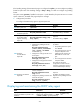
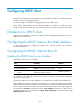
The DHCP server uses Option 121 to assign static route information to DHCP clients.
2424HFigure 123 shows
the format of Option 121. The destination descriptor field comprises two parts, subnet mask length and
destination network address. In this example, the value of the destination descriptor field takes 18 14 01
01, a hexadecimal number indicating that the subnet mask length is 24 and destination network address
is 20.1.1.0, and the value of the next hop address field takes 0A 01 01 02, a hexadecimal number
indicating that the next hop is 10.1.1.2.
Figure 123 Option 121 format
Figure 124 Network diagram
1252BConfiguration procedure
1. Configure Router A:
# Specify the IP address of GigabitEthernet 0/1.
<RouterA> system-view
[RouterA] interface gigabitethernet 0/1
[RouterA-GigabitEthernet0/1] ip address 10.1.1.1 24
[RouterA-GigabitEthernet0/1] quit
# Enable DHCP.
Firewall
DHCP Client
DNS server
Router A
DHCP server
GE0/1
10.1.1.1/24
GE0/1
Router B
10.1.1.2/24 20.1.1.2/24
20.1.1.1/24