
F3726, F3211, F3174, R5135, R3816-HP Firewalls and UTM Devices Network Management Configuration Guide-6PW100

424
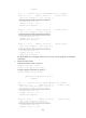
10.1.1.0/24 Direct 0 0 10.1.1.1 GE0/1
10.1.1.1/32 Direct 0 0 127.0.0.1 InLoop0
10.2.1.0/24 Direct 0 0 10.2.1.1 GE0/2
10.2.1.1/32 Direct 0 0 127.0.0.1 InLoop0
10.3.1.0/24 OSPF 10 4 10.1.1.2 GE0/1
10.4.1.0/24 OSPF 10 13 10.2.1.2 GE0/2
127.0.0.0/8 Direct 0 0 127.0.0.1 InLoop0
127.0.0.1/32 Direct 0 0 127.0.0.1 InLoop0
The route to 10.5.1.1/24 is filtered out.
666BBFD for OSPF configuration example
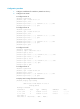
The following matrix shows the configuration example and hardware compatibility:
Hardware Exam
p
le a
pp
licable
F1000-A-EI/F1000-S-EI No
F1000-E No
F5000 Yes
Firewall module No
U200-A No
U200-S No
1450BNetwork requirements
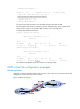
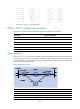
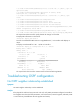
As shown in 2609HFigure 277, run OSPF on Firewall A, Firewall B, and Router so that they can reach each other
at the network layer. When the link over which Firewall A and Firewall B communicate through a Layer
2 switch fails, BFD can quickly detect the failure and notify OSPF of the failure. Firewall A and Firewall
B then communicate through Router.
Figure 277 Network diagram
Device Interface IP address
Device
Interface
IP address
Firewall
A
GE 1/1 192.168.0.102/24
Firewall
B
GE 1/1
192.168.0.100/24
GE 1/2 10.1.1.102
/
24
GE 1/2
13.1.1.1/24
Router GE 1/1 10.1.1.100/24
GE 1/2 13.1.1.2/24