
F3726, F3211, F3174, R5135, R3816-HP Firewalls and UTM Devices Network Management Configuration Guide-6PW100


27
Task Command
Remarks
Display brief IP configuration
information for a specific Layer 3
interface or all Layer 3 interfaces.
display ip interface [ interface-type
[ interface-number ] ] brief [ | { begin |
exclude | include } regular-expression ]
Available in any view.
69B
IP addressing configuration example
1082BNetwork requirements
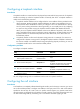
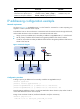
As shown in 2160HFigure 12, GigabitEthernet 0/1 on the firewall is connected to a LAN comprising two
s e g m e n t s : 172.16 .1.0 / 24 a n d 172.16. 2.0 / 24 .
To enable the hosts on the two subnets to communicate with the external network through the firewall,
and to enable the hosts on the two subnets to communicate with each other:
• Assign a primary IP address and a secondary IP address to GigabitEthernet 0/1 on the firewall.
• Set the primary IP address of the firewall as the gateway address of the hosts on subnet
172.16.1.0/24, and the secondary IP address of the firewall as the gateway address of the hosts on
s u b n e t 172.16.2.0 / 24 .
Figure 12 Network diagram
1083BConfiguration procedure
# Assign a primary IP address and a secondary IP address to GigabitEthernet 0/1.
<Firewall> system-view
[Firewall] interface gigabitethernet 0/1
[Firewall-GigabitEthernet0/1] ip address 172.16.1.1 255.255.255.0
[Firewall-GigabitEthernet0/1] ip address 172.16.2.1 255.255.255.0 sub
# Set the gateway address to 172.16.1.1 on the hosts attached to subnet 172.16.1.0/24, and to 172.16.2.1
on the hosts attached to subnet 172.16.2.0/24.
# Ping a host on subnet 172.16.1.0/24 from the firewall to verify the connectivity.
<Firewall> ping 172.16.1.2
PING 172.16.1.2: 56 data bytes, press CTRL_C to break