
F3726, F3211, F3174, R5135, R3816-HP Firewalls and UTM Devices Network Management Configuration Guide-6PW100


624
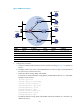
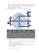
Both POS 5/0 on Router D and GigabitEthernet 0/3 on the firewall act as C-BSRs and C-RPs. The
C-BSR on Router D has a higher priority. The range of multicast groups served by the C-RP is
225.1.1.0/24. Modify the hash mask length to map a certain number of consecutive group
addresses within the range to the two C-RPs.
IGMPv2 runs between Router A and N1 and between Router B, Router C, and N2.
Figure 349 Network diagram
Device Interface IP address
Device
Interface IP address
Router A Eth1/1 10.110.1.1/24 Firewall GE0/1 10.110.5.1/24
Eth1/2 192.168.1.1/24
GE0/2
192.168.1.2/24
POS5/0 192.168.9.1/24
GE0/3
192.168.4.2/24
Router B Eth1/1 10.110.2.1/24 Router D POS5/0 192.168.3.2/24
POS5/0 192.168.2.1/24
POS5/1 192.168.2.2/24
Router C Eth1/1 10.110.2.2/24
POS5/2 192.168.9.2/24
POS5/0 192.168.3.1/24 Eth1/1 192.168.4.1/24
2. Configuration procedure
a. Assign an IP address and subnet mask to each interface according to 2823HFigure 349. (Details not
shown.)
b. Configure OSPF on the routers in the PIM-SM domain to make sure they are interoperable at
the network layer. (Details not shown.)
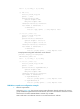
c. Enable IP multicast routing, IGMP, and PIM-SM:
# On Router A, enable IP multicast routing globally, enable IGMP on Ethernet 1/1, and enable
PIM-SM on each interface.
<RouterA> system-view
[RouterA] multicast routing-enable
[RouterA] interface ethernet 1/1
Source
10.110.5.100/24
PIM-SM
Router A
Router B
Router C
Firewall
Receiver
Host A
Host B
Host C
Host D
Receiver
Router D
Eth1/1
Eth1/1
Eth1/1
GE0/1
POS5/0
POS5/2
Et
h
1/2G
E0
/2
POS5/0
POS5/1
POS5/0
POS5/0
Eth1/1
GE0/3