
F3726, F3211, F3174, R5135, R3816-HP Firewalls and UTM Devices Network Management Configuration Guide-6PW100


629
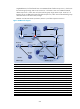
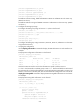
GigabitEthernet 0/2 of the firewall acts as a C-BSR and C-RP of admin-scope zone 1, which serve
the multicast group range 239.0.0.0/8. Serial 2/1 of Router C acts as a C-BSR and C-RP of
admin-scope zone 2, which also serve the multicast group range 239.0.0.0/8. Serial 2/1 of
Router E acts as a C-BSR and a C-RP of the global scope zone, which serve all the multicast groups
other than those in the 239.0.0.0/8 range.
IGMPv2 runs between Router A, Router D, Router H, and their respective receivers.
Figure 350 Network diagram
Device Interface IP address
Device
Interface
IP address
Router A Eth1/1 192.168.1.1/24 Router C S2/1 10.110.4.2/24
Eth1/2 10.110.1.1
/
24
S2/2
10.110.7.1
/
24
Firewall GE0
/
1 192.168.2.1/24
POS5/1
10.110.8.1
/
24
GE0/2 10.110.1.2/24 Router D Eth1/1 192.168.4.1/24
GE0
/
3 10.110.2.1
/
24
S2/1
10.110.5.2
/
24
GE0
/
4 10.110.3.1
/
24
S2/2
10.110.7.2
/
24
Router B Eth1/1 192.168.3.1/24 Router E S2/1 10.110.9.1/24
S2/1 10.110.4.1
/
24
POS5/1
10.110.8.2
/
24
S2/2 10.110.5.1
/
24
Eth1/1
10.110.3.2
/
24
Eth1/2 10.110.2.2/24 Router F Eth1/1 192.168.5.1/24
POS5/2 10.110.6.1
/
24
S2/1
10.110.9.2
/
24
Router G S2/1 10.110.10.1
/
24
Source 1
—
192.168.2.10/24
POS5/1 10.110.6.2/24 Source 2 — 192.168.3.10/24
Router H Eth1/1 192.168.6.1/24
Source 3
—
192.168.5.10/24
S2/1 10.110.10.2
/
24
Router A
Firewall
ZBR
Router B
ZBR
Router C
ZBR
Router D
Router GRouter H
Router E
Router F
Source 3
Source 1
Source 2
Receiver
Host A
S2/1
S2/2
Eth
1/2
Et
h1/1
POS5/2 S2/1
S2/2
POS5/1
POS5/1
S2/1
S2/1
Eth1/1
S2
/1
S2/2
Eth1/1
S2/1
S2/1 POS5/1
Eth
1/1
Eth1/1 GE0/1
GE0/4
GE0/3 Eth1/1Eth1/2
GE0/2
Admin-scope 2
PIM-SM
Global-scope
Admin-scope 1
Receiver
Host B
Receiver
Host C