
F3726, F3211, F3174, R5135, R3816-HP Firewalls and UTM Devices Network Management Configuration Guide-6PW100

649
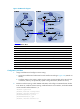
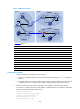
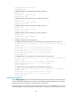
Figure 352 Network diagram
Device Interface IP address
Device
Interface
IP address
Router A Eth1/1 10.110.1.2/24 Router D Eth1/1 10.110.4.2/24
Eth1/2 10.110.2.1/24
Eth1/2
10.110.5.1/24
Eth1/3 10.110.3.1/24
Firewall
GE0/1
10.110.6.1/24
Router B Eth1/1 10.110.1.1/24 GE0/2 192.168.3.2/24
POS5/0 192.168.1.1/24
Loop0
3.3.3.3/32
Loop0 1.1.1.1/32
Router
E
Eth1/1
10.110.6.2/24
Router C Eth1/1 10.110.4.1/24 Eth1/2 10.110.7.1/24
Eth1/2 192.168.3.1/24
Source 1
—
10.110.2.100/24
POS5/0 192.168.1.2/24
Source 2
—
10.110.5.100/24
Loop0 2.2.2.2/32
1643BConfiguration procedure
1. Assign IP addresses and configure unicast routing:
a. Assign the IP address and subnet mask to each interface according to 2842HFigure 352. (Details not
shown.)
b. Configure OSPF on the routers to make sure the routers are interoperable at the network layer
in each AS, and they can dynamically update routing information. (Details not shown.)
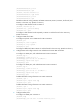
2. Enable IP multicast routing, enable PIM-SM and IGMP, and configure a PIM-SM domain border:
# On Router A, enable IP multicast routing, enable PIM-SM on each interface, and enable IGMP
on the host-side interface Ethernet 1/3.
<RouterA> system-view
[RouterA] multicast routing-enable
[RouterA] interface ethernet 1/1
[RouterA-Ethernet1/1] pim sm
[RouterA-Ethernet1/1] quit
[RouterA] interface ethernet 1/2
Eth1
/
1
Et
h1/1
Eth
1/3
Et
h1/2
Eth1/
2