
F3726, F3211, F3174, R5135, R3816-HP Firewalls and UTM Devices Network Management Configuration Guide-6PW100


658
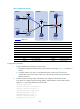
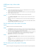
Figure 354 Network diagram
Device Interface IP address Device Interface IP address
Source 1 —
10.110.5.100/24
Router C
POS5/0 192.168.1.2/24
Source 2 —
10.110.6.100/24
Eth1/1
192.168.2.2/24
Router A Eth1/1 10.110.5.1/24 Firewall GE0/1 10.110.3.1/24
S2/0 10.110.2.2/24
GE0/2
10.110.4.1/24
Router B Eth1/1 10.110.1.1/24
GE0/3
192.168.2.1/24
S2/0 10.110.2.1/24 Loop0 2.2.2.2/32
POS5/0 192.168.1.1/24
Loop10
4.4.4.4/32
Loop0 1.1.1.1/32
Loop20
10.1.1.1/32
Loop10 3.3.3.3/32 Router D Eth1/1 10.110.6.1/24
Loop20 10.1.1.1/32
Eth1/2
10.110.4.2/24
1649BConfiguration procedure
1. Assign IP addresses and configure unicast routing:
a. Assign an IP address and subnet mask to each interface according to 2846HFigure 354. (Details not
shown.)
b. Configure OSPF on the routers in the PIM-SM domain to make sure the routers are
interoperable at the network layer and they can dynamically update routing information.
(Details not shown.)
2. Enable IP multicast routing, IGMP, and PIM-SM:
# On Router B, enable IP multicast routing globally, enable IGMP on Ethernet 1/1, and enable
PIM-SM on each interface.
<RouterB> system-view
[RouterB] multicast routing-enable
[RouterB] interface ethernet 1/1
[RouterB-Ethernet1/1] igmp enable
[RouterB-Ethernet1/1] pim sm
[RouterB-Ethernet1/1] quit
L
oo
p0
L
o
op20
Loop
2
0
L
oop
0
P
O
S
5
/
0
P
OS
5
/
0
E
t
h
1
/
1
G
E
0
/
3
S
2
/
0
S
2
/
0
E
t
h
1
/
2
G
E
0
/
2