
F3726, F3211, F3174, R5135, R3816-HP Firewalls and UTM Devices Network Management Configuration Guide-6PW100


788
Hardware Exam
p
le a
pp
licable
U200-S No
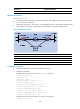
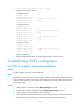
1743BNetwork requirements
As shown in 2956HFigure 395:
• Configure OSPFv3 on Firewall A, Firewall B and Router and configure BFD over the link Firewall
A<—>L2 Switch<—>Firewall B.
• After the link Firewall A<—>L2 Switch<—>Firewall B fails, BFD can quickly detect the failure and
notify OSPFv3 of the failure. Then Firewall A and Firewall B communicate through Router.
Figure 395 Network diagram
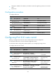
Device Interface IPv6 address Device Interface IPv6 address
Firewall
A
GE1/1 2001::1/64
Firewall
B
GE1/1
2001::2/64
GE1/2 2001:2::1/64 GE1/2 2001:3::2/64
Router GE1/1 2001:2::2/64
GE1/2 2001:3::1/64
1744BConfiguration procedure
1. Configure IP addresses for interfaces. (Details not shown.)
2. Configure basic OSPF:
# Enable OSPFv3 and set the router ID to 1.1.1.1 on Firewall A.
<FirewallA> system-view
[FirewallA] ipv6
[FirewallA] ospfv3 1
[FirewallA-ospfv3-1] router-id 1.1.1.1
[FirewallA-ospfv3-1] quit
[FirewallA] interface gigabitethernet 1/1
[FirewallA-GigabitEthernet1/1] ospfv3 1 area 0
[FirewallA-GigabitEthernet1/1] quit
[FirewallA] interface gigabitethernet 1/2
[FirewallA-GigabitEthernet1/2] ospfv3 1 area 0
[FirewallA-GigabitEthernet1/2] quit
# Enable OSPFv3 and set the router ID to 2.2.2.2 on Firewall B.
<FirewallB> system-view