
F3726, F3211, F3174, R5135, R3816-HP Firewalls and UTM Devices Network Management Configuration Guide-6PW100


60
Ste
p
Actions
2
The device compares the configuration BPDUs of all ports and chooses the optimum configuration
BPDU.
The following are the principles of configuration BPDU comparison:
• The configuration BPDU with the lowest root bridge ID has the highest priority.
• If configuration BPDUs have the same root bridge ID, their root path costs are compared. For
example, the root path cost in a configuration BPDU plus the path cost of a receiving port is S. The
configuration BPDU with the smallest S value has the highest priority.
• If all configuration BPDUs have the same ports value, their designated bridge IDs, designated port
IDs, and the IDs of the receiving ports are compared in sequence. The configuration BPDU that
contains the smallest ID wins.
A tree-shape topology forms when the root bridge, root ports, and designated ports are selected.
An example of STP algorithm calculations:
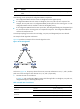
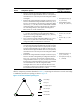
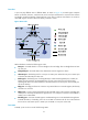
2198HFigure 40 provides an example of how the STP algorithm works.
Figure 40 The STP algorithm
As shown in 2199HFigure 40, the priority values of Device A, Device B, and Device C are 0, 1, and 2, and the
path costs of links among the three devices are 5, 10, and 4, respectively.
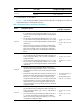
4. Initialize the state on each device.
In
2200HTable 10, each configuration BPDU contains the following fields: root bridge ID, root path cost,
designated bridge ID, and designated port ID.
Table 10 Initial state of each device
Device Port name Confi
g
uration BPDU
on the
p
ort
Device A
Port A1 {0, 0, 0, Port A1}
Port A2 {0, 0, 0, Port A2}
Device B
Port B1 {1, 0, 1, Port B1}
Port B2 {1, 0, 1, Port B2}