
F3726, F3211, F3174, R5135, R3816-HP Firewalls and UTM Devices Network Management Configuration Guide-6PW100


65
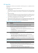
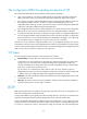
Figure 42 Basic concepts in MSTP
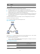
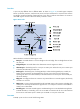
Figure 43 Network diagram and topology of MST region 3
1114BMST region
A multiple spanning tree region (MST region) consists of multiple devices in a switched network and the
network segments among them. All these devices have the following characteristics:
• A spanning tree protocol is enabled.
• Same region name.
MST region 1
MST region 2 MST region 3
MST region 4
VLAN 1 MSTI 1
VLAN 2
MSTI 2
Other VLANs
MSTI 0
VLAN 1 MSTI 1
VLAN 2
MSTI 2
Other VLANs
MSTI 0
VLAN 1 MSTI 1
VLAN 2
MSTI 2
Other VLANs
MSTI 0
VLAN 1 MSTI 1
VLAN 2&3
MSTI 2
Other VLANs
MSTI 0
CST
MST region 3
Device A
Device C
Device B
Device D
VLAN 1 MSTI 1
VLAN 2&3
MSTI 2
Other VLANs
MSTI 0
To MST region 4
To MST region 2
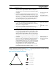
BA
C D
MSTI 1
A B
C D
MSTI 0
B
D
MSTI 2
C
A
Regional root
MSTI
Topology of MSTIs in MST region 3