
F3726, F3211, F3174, R5135, R3816-HP Firewalls and UTM Devices Network Management Configuration Guide-6PW100


76
1126BNetwork requirements
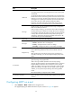
As shown in 2228HFigure 50, all devices on the network are in the same MST region, Device A and Device B
work on the distribution layer, and Device C and Device D work on the access layer.
Configure MSTP so that packets of different VLANs are forwarded along different spanning trees: Packets
of VLAN 10 are forwarded along MSTI 1, those of VLAN 30 are forwarded along MSTI 3, those of VLAN
40 are forwarded along MSTI 4, and those of VLAN 20 are forwarded along MSTI 0.
VLAN 10 and VLAN 30 are terminated on the distribution layer devices, and VLAN 40 is terminated on
the access layer devices, so the root bridges of MSTI 1 and MSTI 3 are Device A and Device B,
respectively, and the root bridge of MSTI 4 is Device C.
Figure 50 Network diagram
Suppose that the VLAN and VLAN member ports configurations have been completed according to the
network diagram:
• Create VLAN 10, VLAN 20, and VLAN 30 on Device A and Device B, respectively, create VLAN
10, VLAN 20, and VLAN 40 on Device C, and create VLAN 20, VLAN 30, and VLAN 40 on
Device D.
• Assign the ports on these devices to related VLANs.
• Configure the security zones to which the combinations of these ports and their permitted VLANs
belong.
1127BConfiguring Device A
1. Configure the MST region name as example, map VLAN 10, VLAN 30, and VLAN 40 to MSTI 1,
MSTI 3, and MSTI 4, respectively, and configure the revision level of the MST region as 0:
a. Select Network > MSTP > Region from the navigation tree.
b. Click Modify.
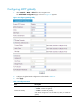
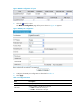
c. Perform the following configurations on the page shown in 2229HFigure 51:
{ Configure the region name as example.
{ Set the revision level to 0.
{ Select the Manual option.
{ Select 1 from the Instance ID list.