
F3726, F3211, F3174, R5135, R3816-HP Firewalls and UTM Devices System Management and Maintenance Configuration Guide-6PW100


127
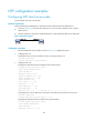
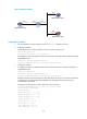
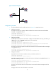
Figure 55 Network diagram
431BConfiguration procedure
1. Set the IP address for each interface as shown in 846HFigure 55. (Details not shown.)
2. Configure Firewall B:
# Specify the local clock as the reference source, with the stratum level 2.
<FirewallB> system-view
[FirewallB] ntp-service refclock-master 2
# Configure Firewall B to operate in multicast server mode and send multicast messages through
GigabitEthernet 0/1.
[FirewallB] interface gigabitethernet 0/1
[FirewallB-GigabitEthernet0/1] ntp-service multicast-server
3. Configure Firewall C:
# Configure Firewall C to operate in multicast client mode and receive multicast messages on
GigabitEthernet 0/1.
<FirewallC> system-view
[FirewallC] interface gigabitethernet 0/1
[FirewallC-GigabitEthernet0/1] ntp-service multicast-client
Because Firewall C and Firewall B are on the same subnet, Firewall C can receive the multicast
messages from Firewall B without being enabled with the multicast functions and can be
synchronized to Firewall B.
# Display the NTP status of Firewall C after clock synchronization.
[FirewallC-GigabitEthernet0/1] display ntp-service status
Clock status: synchronized
Clock stratum: 3
Reference clock ID: 3.0.1.31
Nominal frequency: 64.0000 Hz
Actual frequency: 64.0000 Hz
Clock precision: 2^7
Clock offset: 0.0000 ms
Root delay: 31.00 ms
Root dispersion: 8.31 ms
Peer dispersion: 34.30 ms
GE0/1
1.0.1.10/24
Firewall A
NTP multicast client
GE0/1
3.0.1.31/24
GE0/1
3.0.1.32/24
Device
Firewall B
NTP multicast server
Firewall C
NTP multicast client
GE0/1
1.0.1.11/24
GE0/2
3.0.1.30/24