
F3726, F3211, F3174, R5135, R3816-HP Firewalls and UTM Devices System Management and Maintenance Configuration Guide-6PW100


131
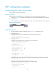
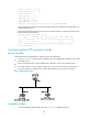
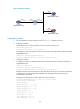
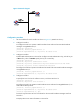
Figure 57 Network diagram
435BConfiguration procedure
1. Set the IP address for each interface as shown in 850HFigure 57. (Details not shown.)
2. Configure Firewall A:
# Configure Firewall A to operate in NTP broadcast client mode and receive NTP broadcast
messages on GigabitEthernet 0/1.
<FirewallA> system-view
[FirewallA] interface gigabitethernet 0/1
[FirewallA-GigabitEthernet0/1] ntp-service broadcast-client
3. Configure Firewall B:
# Enable NTP authentication on Firewall B. Configure an NTP authentication key, with the key ID
of 88 and key value of 123456. Specify the key as a trusted key.
<FirewallB> system-view
[FirewallB] ntp-service authentication enable
[FirewallB] ntp-service authentication-keyid 88 authentication-mode md5 123456
[FirewallB] ntp-service reliable authentication-keyid 88
# Configure Firewall B to operate in broadcast client mode and receive NTP broadcast messages
on GigabitEthernet 0/1.
[FirewallB] interface gigabitethernet 0/1
[FirewallB-GigabitEthernet0/1] ntp-service broadcast-client
4. Configure Firewall C:
# Specify the local clock as the reference source, with the stratum level 3.
<FirewallC> system-view
[FirewallC] ntp-service refclock-master 3
# Configure Firewall C to operate in NTP broadcast server mode and use GigabitEthernet 0/1 to
send NTP broadcast packets.
[FirewallC] interface gigabitethernet 0/1
[FirewallC-GigabitEthernet0/1] ntp-service broadcast-server
[FirewallC-GigabitEthernet0/1] quit
# Firewall A synchronizes its local clock based on the received broadcast messages sent from
Firewall C.
# Display NTP service status information on Firewall A.