
F3726, F3211, F3174, R5135, R3816-HP Firewalls and UTM Devices System Management and Maintenance Configuration Guide-6PW100


202
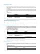
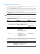
The device selection page appears.
2. Select a VD.
3. Click the Login link.
The Web interface of the target VD appears, where you can perform operations.
Figure 93 Selecting a VD
310BVD configuration example
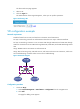
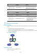
475BNetwork requirements
Divide the firewall into two VDs, and rent them to Customer A and Customer B.
For layer 3 networking, Customer A and Customer B have their own Layer 3 Ethernet interfaces.
For layer 2 networking, Customer A can use VLAN 100 through VLAN 205 and VLAN 300 through
VLAN 310. Customer B can use VLAN 50 through VLAN 80, VLAN 400, and VLAN 500 through VLAN
530.
Assign 100000 sessions to Customer A and Customer B.
Assign 100 real service groups, 200 real services, and 100 virtual services to Customer A, which uses
server load balancing. Customer B does not use server load balancing.
Figure 94 Network diagram
476BConfiguration procedure
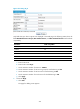
1. Create VD VD_A:
a. Select Device Management > Virtual Device > Configuration from the navigation tree.
b. Click Add.
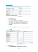
The page for adding a VD appears.