
F3726, F3211, F3174, R5135, R3816-HP Firewalls and UTM Devices VPN Configuration Guide-6PW100

145
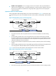
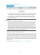
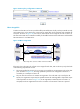
Figure 98 IPsec stateful failover
As shown in 751HFigure 98, Device A and Device B form an IPsec stateful failover system and Device A is
elected the master in the VRRP group. When Device A works normally, it establishes an IPsec tunnel to
Device C, and synchronizes its IPsec service data to Device B. The synchronized IPsec service data
includes the IKE SA, IPsec SAs, anti-replay sequence number and window, SA lifetime in bytes, and DPD
packet sequence number. Based on the IPsec service data, Device B creates standby IKE SA and standby
IPsec SAs to back up the active IKE SA and active IPsec SAs on Device A. When Device A fails, the VRRP
mechanism switches IPsec traffic from Device A to Device B. Because Device B has an instant copy of
Device A's IPsec service data, Device B can immediately process IPsec traffic to provide nonstop IPsec
service.
195BProtocols and standards
• RFC 2401, Security Architecture for the Internet Protocol
• RFC 2402, IP Authentication Header
• RFC 2406, IP Encapsulating Security Payload
• RFC 4552, Authentication/Confidentiality for OSPFv3
• RFC4301, Security Architecture for the Internet Protocol
• RFC4302, IP Authentication Header
• RFC4303, IP Encapsulating Security Payload (ESP)
41B
Configuration guidelines
When you configure IPsec, follow these guidelines:
• Typically, IKE uses UDP port 500 for communication, and AH and ESP use the protocol numbers 51
and 50, respectively. You must make sure flows of these protocols are not denied on the interfaces
with IKE or IPsec configured.
LAN
Device A
Device B
Device C
Failover link
Master Backup
Virtual router 1
Virtual router 2
I
P
s
e
c
t
u
n
n
e
l
LAN
Internet