
F3726, F3211, F3174, R5135, R3816-HP Firewalls and UTM Devices VPN Configuration Guide-6PW100

7
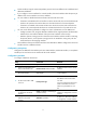
Item Descri
p
tion
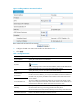
Keepalive
Enable or disable the GRE keepalive function.
With the GRE keepalive function enabled on a tunnel interface, the device sends
GRE keepalive packets from the tunnel interface periodically. If no response is
received from the peer within the specified interval, the device retransmits the
keepalive packet. If the device still receives no response from the peer after sending
the keepalive packet for the maximum number of attempts, the local tunnel interface
goes down and stays down until it receives a keepalive acknowledgement packet
from the peer.
Keepalive Interval
Specify the interval between sending the keepalive packets.
This configuration item is available when you select Enable for the GRE keepalive
function.
Number of Retries
Set the maximum number of transmission attempts.
This configuration item is available when you select Enable for the GRE keepalive
function.
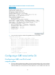
100BGRE over IPv4 tunnel configuration example
328BNetwork requirements
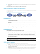
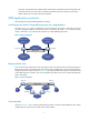
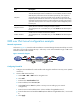
As shown in 673HFigure 10, Firewall A and Firewall B are connected through the Internet and they can reach
each other. Two private IP subnets Group 1 and Group 2 are interconnected through a GRE tunnel
between Firewall A and Firewall B.
Figure 10 Network diagram
329BConfiguring Firewall A
1. Configure an IPv4 address for each interface and assign the interfaces to security zones. (Details
not shown.)
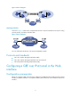
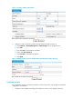
2. Create a GRE tunnel interface:
a. Select VPN > GRE > GRE from the navigation tree.
b. Click Add.
c. Enter 0 in the Tunnel Interface field.
d. Enter IP address/mask 10.1.2.1/24.
e. Select Trust from the Zone list. (Select a security zone according to your network
configuration.)
f. Enter the source end IP address 1.1.1.1, the IP address of GigabitEthernet 0/1.
g. Enter the destination end IP address 2.2.2.2, the IP address of GigabitEthernet 0/1 on Firewall
B.
h. Click Apply.