
F3726, F3211, F3174, R5135, R3816-HP Firewalls and UTM Devices VPN Configuration Guide-6PW100

203
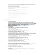
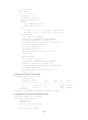
2.2.2.0/24 Static 60 0 1.1.1.2 GE0/1
10.4.4.0/24 Direct 0 0 10.4.4.1 GE0/2
10.4.4.4/32 Direct 0 0 127.0.0.1 InLoop0
10.5.5.0/24 Static 60 0 1.1.1.2 GE0/1
127.0.0.0/8 Direct 0 0 127.0.0.1 InLoop0
127.0.0.1/32 Direct 0 0 127.0.0.1 InLoop0
The output shows that IPsec RRI has created a static route to subnet 10.5.5.0/24 with the next hop
1.1.1.2.
# Delete the IPsec SAs.
The static route is automatically deleted.
217BIPsec stateful failover configuration example
The following matrix shows the configuration example and hardware compatibility:
Hardware Exam
p
le a
pp
licable
F1000-A-EI/F1000-S-EI Yes
F1000-E Yes
F5000 Yes
Firewall module Yes
U200-A No
U200-S No
467BNetwork requirements
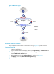
As shown in 808HFigure 132, a network has two gateways, Firewall A and Firewall B, at the headquarters.
Configure an IPsec tunnel between the headquarters and the branch for secure communication, and
complete the following tasks to configure IPsec stateful failover on Firewall A and Firewall B for high
availability of the IPsec tunnel:
• Deploy a physical link for IPsec service data backup between Firewall A and Firewall B, and
configure the connecting interfaces as failover interfaces.
• On Firewall A and Firewall B, add the uplink interface to VRRP group 2 and the downlink interface
to VRRP group 1, and assign the virtual IP address 192.168.0.1/24 to VRRP group 2 and the virtual
IP address 10.1.1.1/2 to VRRP group 1.
• Use Firewall A as the master device to establish an IPsec tunnel with Firewall C and make sure that
Firewall B takes over when Firewall A fails.