
F3726, F3211, F3174, R5135, R3816-HP Firewalls and UTM Devices VPN Configuration Guide-6PW100

15
For more information about commands display interface tunnel and display ipv6 interface tunnel, see
VPN Command Reference.
104BGRE over IPv4 tunnel configuration examplel
338BNetwork requirements
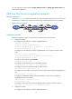
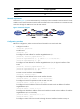
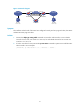
As shown in 675HFigure 14, Firewall A and Firewall B are interconnected through the Internet. Two private IPv4
subnets Group 1 and Group 2 are interconnected through a GRE tunnel between the two firewalls.
Figure 14 Network diagram
339BConfiguration procedure
Before the configuration, make sure Firewall A and Firewall B can reach each other.
1. Configure Firewall A:
# Configure an IPv4 address for interface GigabitEthernet 0/1.
<FirewallA> system-view
[FirewallA] interface gigabitethernet 0/1
[FirewallA-GigabitEthernet0/1] ip address 10.1.1.1 255.255.255.0
[FirewallA-GigabitEthernet0/1] quit
# Configure an IPv4 address for interface GigabitEthernet 0/2, the physical interface of the
tunnel.
[FirewallA] interface gigabitethernet 0/2
[FirewallA-GigabitEthernet0/2] ip address 1.1.1.1 255.255.255.0
[FirewallA-GigabitEthernet0/2] quit
# Create a tunnel interface named Tunnel0.
[FirewallA] interface tunnel 0
# Configure an IPv4 address for the tunnel interface Tunnel0.
[FirewallA-Tunnel0] ip address 10.1.2.1 255.255.255.0
# Configure the tunnel encapsulation mode as GRE over IPv4.
[FirewallA-Tunnel0] tunnel-protocol gre
# Configure the source address of the tunnel interface Tunnel0 as the IP address of GigabitEthernet
0/2.
[FirewallA-Tunnel0] source 1.1.1.1
# Configure the destination address of the tunnel interface Tunnel0 as the IP address of
GigabitEthernet 0/2 on Firewall B.
[FirewallA-Tunnel0] destination 2.2.2.2
[FirewallA-Tunnel0] quit
# Configure a static route from Firewall A through the tunnel interface Tunnel0 to Group 2.
[FirewallA] ip route-static 10.1.3.0 255.255.255.0 tunnel 0
2. Configure Firewall B:
# Configure an IPv4 address for interface GigabitEthernet 0/1.