
F3726, F3211, F3174, R5135, R3816-HP Firewalls and UTM Devices VPN Configuration Guide-6PW100

18
Hardware Exam
p
le a
pp
licable
U200-A Yes
U200-S No
340BNetwork requirements
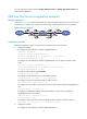
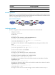
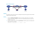
As shown in 676HFigure 15, two IPv4 subnets Group 1 and Group 2 are connected to an IPv6 network. Create
a GRE over IPv6 tunnel between Firewall A and Firewall B so the two IPv4 subnets can communicate with
each other through the GRE tunnel over the IPv6 network.
Figure 15 Network diagram
341BConfiguration procedure
Before the configuration, make sure Firewall A and Firewall B can reach each other.
1. Configure Firewall A:
<FirewallA> system-view
# Enable IPv6.
[FirewallA] ipv6
# Configure an IPv4 address for interface GigabitEthernet 0/1.
[FirewallA] interface gigabitethernet 0/1
[FirewallA-GigabitEthernet0/1] ip address 10.1.1.1 255.255.255.0
[FirewallA-GigabitEthernet0/1] quit
# Configure an IPv6 address for interface GigabitEthernet 0/2, the physical interface of the
tunnel.
[FirewallA] interface gigabitethernet 0/2
[FirewallA-GigabitEthernet0/2] ipv6 address 2002::1:1 64
[FirewallA-GigabitEthernet0/2] quit
# Create a tunnel interface named Tunnel0.
[FirewallA] interface tunnel 0
# Configure an IPv4 address for the tunnel interface Tunnel0.
[FirewallA-Tunnel0] ip address 10.1.2.1 255.255.255.0
# Configure the tunnel encapsulation mode as GRE over IPv6.
[FirewallA-Tunnel0] tunnel-protocol gre ipv6
# Configure the source address of the tunnel interface Tunnel0 as the IP address of interface
GigabitEthernet 0/2.
[FirewallA-Tunnel0] source 2002::1:1
# Configure the destination address of the tunnel interface Tunnel0 as the IP address of interface
GigabitEthernet 0/2 on Firewall B).
[FirewallA-Tunnel0] destination 2001::2:1
[FirewallA-Tunnel0] quit
# Configure a static route from Firewall A through the tunnel interface Tunnel0 to Group 2.