
F3726, F3211, F3174, R5135, R3816-HP Firewalls and UTM Devices VPN Configuration Guide-6PW100


29
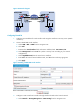
Figure 23 Tunnel list
Table 3 Field description
Field Descri
p
tion
Tunnel Interface Name of the tunnel interface.
Tunnel Dest Address IP address of the tunnel destination.
Branch Network
Address/Mask
IP address and mask of the branch network.
GRE Key
GRE key of the tunnel, used to identify the priority of the tunnel entry. If the tunnel
peer device is not configured with a GRE key, nothing will be displayed for this
field.
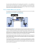
114BBasic P2MP GRE tunnel configuration example
344BNetwork requirements
A company has a network at the headquarters and each of its branches. It is required to implement
communication between the headquarters and the branches through GRE.
685HFigure 24 shows a simplified
scenario, where there is only one branch.
• Firewall A is the gateway at the headquarters, and Firewall B is the gateway of the branch.
• Host A is an internal user at the headquarters and Host B is an internal user at the branch. A GRE
tunnel is established between Firewall A and Firewall B to implement communication between Host
A and Host B.
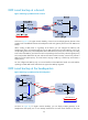
If you use P2P GRE tunnels, the number of GRE tunnels to be configured is the same as that of the
branches. To simplify the configuration at the headquarters, you can create a P2MP GRE tunnel interface
on Firewall A, and configure a GRE over IPv4 tunnel interface on Firewall B.
This example uses Firewall B to illustrate the branch gateway configuration. The configuration on other
branch gateways is similar.