
F3726, F3211, F3174, R5135, R3816-HP Firewalls and UTM Devices VPN Configuration Guide-6PW100

31
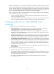
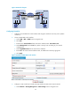
b. Click Add.
c. Enter 192.168.12.0 as the destination IP address.
d. Select mask 255.255.255.0.
e. Select Tunnel0 as the outbound interface.
f. Click Apply.
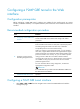
Figure 26 Adding a static route from Firewall A through interface Tunnel0 to the branch network
346BConfiguring Firewall B
1. Configure an IPv4 address for each interface and assign the interfaces to security zones. (Details
not shown.)
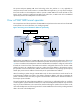
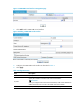
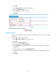
2. Create a GRE over IPv4 tunnel interface:
a. Select VPN > GRE > GRE from the navigation tree.
b. Click Add.
c. Enter 0 in the Tunnel Interface field.
d. Enter IP address/mask 192.168.22.2/24.
e. Select Management from the Zone list. (Select a security zone according to your network
configuration.)
f. Select the tunnel source interface GigabitEthernet 0/1.
g. Enter the tunnel destination IP address 11.1.1.1, the IP address of GigabitEthernet 0/1 on
Firewall A.
h. Click Apply.