
F3726, F3211, F3174, R5135, R3816-HP Firewalls and UTM Devices VPN Configuration Guide-6PW100

43
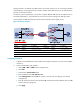
allowing Firewall A to establish two GRE tunnels to the branch network, one for connecting Firewall B
and the other for connecting Firewall C. Firewall A decides which GRE tunnel to use to send packets to
the hosts on the branch network.
To meet the previous requirements, you need to configure different GRE keys for the GRE tunnels on
Firewall B and Firewall C, so that Firewall A can choose a tunnel according to the GRE key values.
In this example, the GRE tunnel between Firewall A and Firewall B has a higher priority.
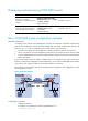
Figure 43 Network diagram
Device Interface IP address
Device
Interface
IP address
Firewall A GE0/1 11.1.1.1/24 Firewall B GE0/1 11.1.1.2/24
GE0/2 172.17.17.1/24
GE0/2
192.168.1.2
/
24
Tunnel0 192.168.22.1/24
Tunnel0
192.168.22.2/24
Firewall C GE0/1 11.1.1.3/24 Firewall C Tunnel0 192.168.22.3/24
GE0/2 192.168.1.3
/
24
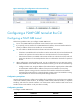
354BConfiguring Firewall A
1. Configure an IPv4 address for each interface and assign the interfaces to security zones. (Details
not shown.)
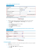
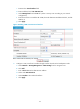
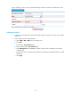
2. Create a P2MP GRE tunnel interface:
a. Select VPN > GRE > P2MP from the navigation tree.
b. Click Add.
c. Enter 0 in the Tunnel Interface field.
d. Enter IP address/mask 192.168.22.1/24.
e. Select Management from the Zone list. (Select a security zone according to your network
configuration.)
f. Enter 11.1.1.1 as the tunnel source interface, 24 as the branch network address mask, and 10
as the tunnel entry aging time.
g. Click Apply.