
F3726, F3211, F3174, R5135, R3816-HP Firewalls and UTM Devices VPN Configuration Guide-6PW100


51
118BDisplaying and maintaining P2MP GRE tunnels
Task Command
Remarks
Display the tunnel entry
information of a P2MP GRE tunnel
interface.
display gre p2mp tunnel-table
interface tunnel number [ | { begin
| exclude | include }
regular-expression ]
Available in any view.
Clear the tunnel entry information
of a P2MP GRE tunnel interface.
reset gre p2mp tunnel-table
[ interface tunnel number
[ dest-address
tunnel-dest-address] ]
Available in user view.
119BBasic P2MP GRE tunnel configuration example
360BNetwork requirements
A company has a network at the headquarters and each of its branches. Implement communication
between the headquarters and the branches through GRE, but forbid communication between the
branches.
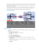
690HFigure 53 shows a simplified scenario, where there is only one branch.
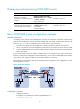
• Firewall A is the gateway at the headquarters, and Firewall B is the gateway of the branch.
• Host A is an internal user at the headquarters and Host B is an internal user at the branch. A GRE
tunnel is established between Firewall A and Firewall B to implement intercommunication between
Host A and Host B.
If you use P2P GRE tunnels, the number of GRE tunnels to be configured is the same as that of the
branches. To simplify the configuration at the headquarters, you can create a P2MP GRE tunnel interface
on Firewall A, and configure a GRE over IPv4 tunnel interface on Firewall B.
This example uses Firewall B to illustrate the branch gateway configuration. The configuration on other
branch gateways is similar.
Figure 53 Network diagram
361BConfiguration procedure
1. Configure Firewall A:
# Configure an IP address for interface GigabitEthernet 0/1.
<FirewallA> system-view