
F3726, F3211, F3174, R5135, R3816-HP Firewalls and UTM Devices VPN Configuration Guide-6PW100
59
[FirewallC-Tunnel0] source 11.1.1.3
[FirewallC-Tunnel0] destination 11.1.1.1
# Set the GRE key of the tunnel interface Tunnel0 to 2.
[FirewallC-Tunnel0] gre key 2
[FirewallC-Tunnel0] quit
# Configure a static route to the headquarters network with the outgoing interface being the tunnel
interface Tunnel0.
[FirewallC] ip route-static 172.17.17.0 255.255.255.0 tunnel 0
5. Verify the configuration:
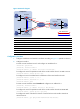
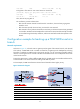
# On Host B, specify Firewall C as the default gateway. Ping Host A from Host B. The ping
operation succeeds. View tunnel entries on Firewall A:
[FirewallA] display gre p2mp tunnel-table interface tunnel 0
Dest Addr Mask Tunnel Dest Addr Gre Key
192.168.1.0 255.255.255.0 11.1.1.3 2
# On Host B, specify Firewall B as the default gateway.Ping Host A from Host B. The ping
operation succeeds. View tunnel entries on Firewall A:
[FirewallA] display gre p2mp tunnel-table interface tunnel 0
Dest Addr Mask Tunnel Dest Addr Gre Key
192.168.1.0 255.255.255.0 11.1.1.3 2
192.168.1.0 255.255.255.0 11.1.1.2 1
The output indicates that Firewall A has two tunnel entries to the branch network and prefers the
tunnel entry with a smaller GRE key value. Packets are forwarded to hosts on the branch network
through Firewall B first.
# On Firewall B, shut down the tunnel interface Tunnel0 to cut off the tunnel link between Firewall
A and Firewall B.
[FirewallB] interface tunnel 0
[FirewallB-Tunnel0] shutdown
# On Host B, specify Firewall C as the default gateway. After the tunnel entry corresponding to
Firewall B ages out, ping Host A from Host B. The ping operation succeeds. View tunnel entries on
Firewall A:
[FirewallA] display gre p2mp tunnel-table interface tunnel 0
Dest Addr Mask Tunnel Dest Addr Gre Key
192.168.1.0 24 11.1.1.3 2
The output indicates that after the link between Firewall A and Firewall B fails, Firewall A has only
the tunnel entry that uses Firewall C to forward packets to the branch network.