
HP A8800 Load Balancing Card Manual-6P102
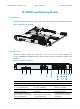

Manual Version: 6P102-20111130 BOM:
3123A0FC
Part number: 5998-2246
iii
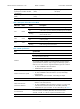
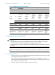
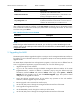
Table 3 1000BASE-X SFP interface specifications
Item S
p
ecification
Connector SFP/LC
Interface standards 802.3, 802.3u, and 802.3ab
Optical
transmit
power
Type
Short-haul
multi-mode
(850 nm)
Optical
interface
module
Mid-haul
single-mode
(1310 nm)
Optical
interface
module
Long-haul
(1310 nm)
Optical
interface
module
Long-haul
(1550 nm)
Optical
interface
module
Extra-long-h
aul (1550
nm) Optical
interface
module
Min –9.5dBm –9dBm –2dBm –4dBm –4dBm
Max 0dBm –3dBm 5dBm 1dBm 2dBm
Reception sensitivity –17dBm –20dBm –23dBm –21dBm –22dBm
Central wavelength 850nm 1310nm 1310nm 1550nm 1550nm
Fiber type
62.5/125μm
MM fiber
9/125μm SM
fiber
9/125μm SM
fiber
9/125μm SM
fiber
9/125μm
SM fiber
Max transmission
distance
0.55 km (0.34
miles)
10 km (6.21
miles)
40 km (24.86
miles)
40 km (24.86
miles)
70 km
(43.50
miles)
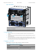
3 Installing and removing the IM-LB
W
ARNING!
• Wear an ESD-preventive wrist strap and ESD-preventive gloves before installing or removing the
module, and make sure that the ESD-preventive wrist strap is properly grounded.
• Avoid touching any components on the PCB and hold the PCB by its edge when installing and removin
g
the module.
NOTE:
The IM-LB is hot swappable. That is, you can remove the module from a router when the router is powered
on.
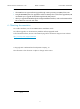
3.1
Installing the IM-LB
1. Locate the slot where you will install the IM-LB, and remove the blank panel from the position. This
manual describes installing the IM-LB to slot 2.
2. Push the IM-LB (with the components facing on) into the slot along the guide rails until the
positioning hole of the module is seated onto the positioning pin on the backplane. Push the ejector
levers inward to lock the IM-LB in place.
3. Fasten the captive screws on the IM-LB with a Philips screwdriver.