
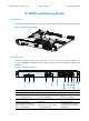
HP A8800 Load Balancing Card Manual-6P102

Manual Version: 6P102-20111130 BOM:
3123A0FC
Part number: 5998-2246
iv
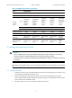
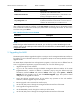
Figure 3 Insert the IM-LB
(1) Push the IM-LB into the slot along the guide rails until the positioning hole of the module is seated onto the
positionin
g
pin on the backplane.
(2) Push the ejector levers inward to lock the IM-LB
in place.
3.2
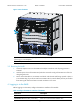
Removing the IM-LB
1. Loosen the captive screws on the IM-LB with a Philips screwdriver until all spring pressure is
released.
2. Hold the ejector levers of the IM-LB and push them outward. Gently pull the IM-LB out of the slot
along the guide rails.
3. Put the removed module on an antistatic workbench with the PCB side facing upward or place it
in an antistatic bag. If you do not install a new IM-LB in the slot, install a blank panel to prevent dust
from entering the chassis and ensure normal ventilation in the router.
4 Logging in to the IM-LB
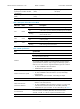
Before logging in to the IM-LB, configure the AUX user interface of the module.
Table 4 Configure the AUX user interface of the IM-LB
Commands Descri
p
tion
system-view Available in user view.
user-interface aux first-number [ last-number ] Enter one or more AUX user interface views
1
2
2