HP High-End Firewalls Attack Protection Configuration Guide Part number: 5998-2630 Software version: F1000-E/Firewall module: R3166 F5000-A5: R3206 Document version: 6PW101-20120706
Legal and notice information © Copyright 2012 Hewlett-Packard Development Company, L.P. No part of this documentation may be reproduced or transmitted in any form or by any means without prior written consent of Hewlett-Packard Development Company, L.P. The information contained herein is subject to change without notice.
Contents Blacklist configuration ·················································································································································· 1 Blacklist overview ······························································································································································ 1 Configuring the blacklist feature·····················································································································
ARP attack protection configuration ························································································································· 32 Configuring periodic sending of gratuitous ARP packets ·························································································· 32 Introduction to periodic sending of gratuitous ARP packets ············································································· 32 Configuring periodic sending of gratuitous ARP packets ·······
Invalid blocking suffix ··········································································································································· 62 ACL configuration failed ······································································································································· 62 Unable to access website by IP address ············································································································· 62 Support and other resources
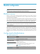
Blacklist configuration NOTE: The firewall supports configuring the blacklist feature only in the web interface. Blacklist overview Blacklist is an attack prevention mechanism that filters packets based on source IP address. Compared with ACL-based packet filtering, the blacklist feature is easier to configure and fast in filtering packets sourced from particular IP addresses. The firewall can cooperate with the scanning detection feature to dynamically add and remove blacklist entries.
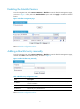
Enabling the blacklist feature From the navigation tree, select Intrusion Detection > Blacklist to enter the blacklist management page, as shown in Figure 1. Then, select the Enable Blacklist option and click Apply to enable the blacklist feature. Figure 1 Blacklist management page Return to Blacklist configuration task list.
Viewing the blacklist From the navigation tree, select Intrusion Detection > Blacklist to enter the blacklist management page, where you can view the blacklist information, as shown in Figure 1. Table 3 Blacklist fields Field Description IP Address Blacklisted IP address Type of the blacklist entry, which can be: Add Method • Auto—Added by the scanning detection feature automatically. • Manual—Added manually or modified manually. Start Time Time when the blacklist entry starts to take effect.
Configuration verification To verify the configurations, perform the following operations: • Selecting Log Report > Report > Blacklist Log from the navigation tree to check where there are logs for the newly added blacklist entry. • Check whether Host A can ping Host B within 100 minutes after the entry was added.
Packet inspection configuration NOTE: The firewall supports configuring packet inspection only in the web interface. Packet inspection overview A single-packet attack, or malformed packet attack, occurs when either of the following events occurs: • An attacker sends defective IP packets, such as overlapping IP fragments and packets with illegal TCP flags, to a target system, making the target system malfunction or crash when processing such packets.
Attack type Description Tracert The Tracert program usually sends UDP packets with a large destination port number and an increasing TTL (starting from 1). The TTL of a packet is decreased by 1 when the packet passes each firewall. Upon receiving a packet with a TTL of 0, a firewall must send an ICMP time exceeded message back to the source IP address of the packet. A Tracert attacker exploits the Tracert program to figure out the network topology.
Item Description Discard Packets when the specified attack is detected Select this option to discard detected attack packets. Enable Fraggle Attack Detection Enable or disable detection of Fraggle attacks. Enable Land Attack Detection Enable or disable detection of Land attacks. Enable WinNuke Attack Detection Enable or disable detection of WinNuke attacks. Enable TCP Flag Attack Detection Enable or disable detection of TCP flag attacks.
1. From the navigation tree, select Device Management > Interface. 2. Assign IP address 192.168.1.2/24 to interface GigabitEthernet 0/0. 3. Assign IP address 10.110.1.2/24 to interface GigabitEthernet 0/1. 4. Assign IP address 202.1.0.1/24 to interface GigabitEthernet 0/2. # Assign the interfaces to security zones. 1. From the navigation tree, select Device Management > Zone. 2. Assign interface GigabitEthernet 0/0 to the trusted zone. 3. Assign interface GigabitEthernet 0/1 to the DMZ zone.
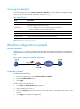
Traffic abnormality detection configuration NOTE: The firewall supports configuring traffic abnormality detection only in the web interface. Traffic abnormality detection overview The traffic abnormality detection feature analyzes the characteristics of traffic to detect abnormal traffic, such as flood attacks and scanning attacks, and to take countermeasures accordingly.
Connection limit Connection limit limits the number of connections based on source IP address or destination IP address. You can set a connection threshold for an IP address on your firewall. Once the number of connections of that IP address exceeds the threshold, the firewall outputs an attack alarm log and, depending on your configuration, blocks the subsequent connection requests from or to that IP address.
Figure 6 ICMP flood detection configuration page Do the following to configure ICMP flood detection: 1. In the Attack Prevention Policy section, specify the protection action to be taken upon detection of an ICMP flood attack. If you do not select the Discard packets when the specified attack is detected option, the firewall only collects ICMP flood attack statistics. 2.
Configuring UDP flood detection From the navigation tree, select Intrusion Detection > Traffic Abnormality > UDP Flood to enter the UDP flood detection configuration page, as shown in Figure 8. You can select a security zone and then view and configure UDP flood detection rules for the security zone. Figure 8 UDP flood detection configuration page Do the following to configure UDP flood detection: 1.
Item Global Configuration of Security Zone Description Connection Rate Threshold Set the global maximum UDP connection rate for each host in the current security zone. NOTE: • In a security zone, you can configure multiple protected hosts and one global connection rate threshold. • For a host, the host-specific setting takes precedence over the global setting of the security zone in case conflict occurs.
entry gets aged out. If you select this option, it is good practice to configure the TCP proxy feature on the page you can enter after selecting Intrusion Detection > TCP Proxy. 2. In the SYN Flood Configuration section, view the configured SYN flood detection rules, or click Add to enter the page shown in Figure 11 to configure a SYN flood detection rule.
Figure 12 Connection limit configuration page Table 9 Connection limit configuration items Item Description Security Zone Select a security zone to which the connection limit configuration will apply. Discard packets when the specified attack is detected Select this option to block connections destined for or sourced from an IP address when the number of the connections for that IP address has exceeded the limit.
Item Description Scanning Threshold Enable Scanning Detection Set the maximum connection rate for a source IP address. Select this option to allow the system to blacklist a suspicious source IP address. Add a source IP to the blacklist If this option is selected, you can then set the lifetime of the blacklisted source IP addresses. Lifetime Set the lifetime of the blacklist entry.
4. Assign interface GigabitEthernet 0/2 to the untrusted zone. # Enable SYN Flood detection. 1. From the navigation tree, select Intrusion Detection > Traffic Abnormality > SYN Flood. 2. Select DMZ from the Security Zone dropdown list. 3. In the Attack Prevention Policy section, select the Discard packets when the specified attack is detected option. 4. Click Apply. 5. In the SYN Flood Configuration section, click Add. 6. On the page that appears, select the Protected Host Configuration option.
URPF Configuration NOTE: • The term router and router icons in this document refers to a routing device running routing protocols in a generic sense. • The firewall supports configuring URPF only in the web interface. URPF overview What is URPF Unicast Reverse Path Forwarding (URPF) protects a network against source address spoofing attacks. Attackers launch such attacks by sending a large number of packets with forged source addresses.
• If the default route is available but the allow-default-route option is not selected, the packet is rejected no matter which check approach is taken. • If the default route is available and the allow-default-route option is selected, URPF operates depending on the check approach. In strict approach, URPF lets the packet pass if the outgoing interface of the default route is the receiving interface, and otherwise rejects it. In loose approach, URPF lets the packet pass directly.
TCP proxy configuration NOTE: The firewall supports TCP proxy configuration only in the web interface. Overview SYN flood attack As a general rule, the establishment of a TCP connection is a three-way handshake: 1. The request originator sends a SYN message to the target server. 2. After receiving the SYN message, the target server establishes a TCP connection in the SYN_RECEIVED state, returns a SYN ACK message to the originator, and waits for a response. 3.
Figure 17 Network diagram for unidirectional proxy As shown in Figure 18, all packets between the TCP client and TCP server go through the TCP proxy, and thus you can configure unidirectional proxy or bidirectional proxy as desired. Figure 18 Network diagram for unidirectional/bidirectional proxy How TCP proxy works Unidirectional proxy Figure 19 shows the data exchange process of unidirectional proxy.
between the client and the server. After the TCP connection is established, the TCP proxy forwards the subsequent packets of the connection without additional processing. Bidirectional proxy Figure 20 shows the data exchange process of bidirectional proxy.
Task Remarks At least one method is required. Adding a protected IP address entry You can add protected IP address entries by either of the methods: • Static: Add entries manually. By default, no such entries are configured in the system. • Dynamic: Select Intrusion Detection > Traffic Abnormality > SYN Flood, and then select the Add protected IP entry to TCP Proxy check box.
Return to TCP proxy configuration task list. Adding a protected IP address entry Select Intrusion Detection > TCP Proxy > Protected IP Configuration to enter the page shown in Figure 22, which lists information about protected IP address entries and the relative statistics. Click Add to enter the page for configuring a protected IP address entry, as shown in Figure 23.
Item Description Destination port of the TCP connection. Port Number The option any specifies that TCP proxy services TCP connection requests to any port of the server at the destination IP address. Type The protected IP address entries can be static or dynamic. Lifetime(min) Lifetime for the IP address entry under protection. This item is displayed as – for static IP address entries. When the time reaches 0, the protected IP address entry will be deleted.
• Type 20.0.0.10 in the Protected IP Address text box. • Select any from the port list. • Click Apply. # Configure the SYN flood detection feature, specifying to automatically add protected IP address entries. • Select Intrusion Detection > Traffic Abnormality > SYN Flood from the navigation tree. • Select Trust from the Security Zone drop-down list. • Select the Add protected IP entry to TCP Proxy check box in the Attack Prevention Policy area. • Click Apply.
IDS collaboration configuration NOTE: • The firewall can collaborate with only Venusense IDS devices. • The firewall supports the IDS collaboration configuration only in the web interface. Overview IDS collaboration is introduced for firewalls to work with an Intrusion detection system (IDS) device. As shown in Figure 25, the collaboration process occurs: 1. The IDS device examines network traffic for attacks. 2.
2. The aging time for an IDS blocking entry is five minutes. The timer restarts if the firewall receives an SNMP trap with the same attack information before the timer expires. 3. A blocking entry is effective only to subsequent connections matching this entry. To make entries apply to the current connections, disable the fast forwarding function of the firewall. 4. Disabling IDS collaboration will remove the generated blocking entries from the firewall.
Intrusion detection statistics Overview Intrusion detection is an important network security feature. By analyzing the contents and behaviors of packets passing by, this feature can determine whether the packets are attack packets and take actions accordingly as configured. Supported actions include outputting alarm logs, discarding packets, and updating session status.
Figure 27 Intrusion detection statistics Table 16 Description of attack types Attack type Description Fraggle A Fraggle attack occurs when an attacker sends large amounts of UDP echo requests with the UDP port number being 7 or Chargen packets with the UDP port number being 19, resulting in a large quantity of junk replies and finally exhausting the bandwidth of the target network.
Attack type Description Source Route A source route attack exploits the source route option in the IP header to probe the topology of a network. Smurf A Smurf attacker sends large quantities of ICMP echo requests to the broadcast address of the target network. As a result, all hosts on the target network will reply to the requests, causing the network congested and hosts on the target network unable to provide services. TCP Flag Some TCP flags are processed differently on different operating systems.
ARP attack protection configuration The Address Resolution Protocol (ARP) is easy to use, but it is often exploited by attackers because of its lack of security mechanism. ARP attacks and ARP viruses bring big threats to LANs. To avoid such attacks and viruses, the firewall provides multiple techniques to detect and prevent them. The following describes the principles and configuration of these techniques.
Table 17 Configuration items of periodic sending of gratuitous ARP packets Item Description Specify an interface and interval for periodically sending gratuitous ARP packets. Select an interface from the Standby Interface list, set its sending interval, and then click << to add it to the Sending Interface list box. To delete the combination of an interface and its sending interval, select it from the Sending Interface list and click >>.
Select Firewall > ARP Anti-Attack > Scan from the navigation tree to enter the ARP scanning configuration page, as shown in Figure 29. Figure 29 ARP scanning Table 18 ARP automatic scanning configuration items Item Description Interface Select the interface to be configured to perform ARP automatic scanning.
To do… Use the command… Remarks Return to system view quit — NOTE: • IP addresses already existent in ARP entries are not scanned. • ARP automatic scanning may take some time. To stop an ongoing scan, press Ctrl + C. Dynamic ARP entries are created based on ARP replies received before the scan is terminated. Configuring fixed ARP Introduction to fixed ARP This feature allows the firewall to convert dynamic ARP entries into static ones.
• Select the checkbox before dynamic ARP entries, and click Fix to convert the selected ARP entry to a static ARP entry. • Select the checkbox before static ARP entries, and click Del Fixed to delete the selected static ARP entry. If you select a dynamic one and click Del Fixed, the entry will not be deleted.
Figure 31 Network diagram of ARP automatic scanning Configuration procedure # Configure IP addresses for the interfaces. (Omitted) # Configure periodic sending of gratuitous ARP packets. • Select Firewall > ARP Anti-Attack > Send Gratuitous ARP from the navigation tree. • Select GigabitEthernet0/3 from the Standby Interface list. • Click << to add the interface to the Sending Interface list. • Click Apply to complete the configuration.
Web filtering configuration Web filtering overview In conventional network security solutions, network protection is mainly against external attacks. With the popularity of network applications in every walk of life, however, more and more internal attacks appear. This requires network devices to construct a secure internal network and enhance the security of the internal network.
the websites, so that the system will forward only the web requests that use the specified IP addresses for website access. IP address-supported URL address filtering NOTE: You can configure this feature only in the command line interface (CLI). Overview After the URL address filtering function is enabled, the system denies all web requests that use IP addresses by default.
• If the parameters are transmitted by the method of Get, Post or Put, the device compares the URL parameters against the configured filtering keywords. If a match is found, the device denies the request; otherwise, the device forwards the request. Java blocking Overview Java blocking can protect networks from being attacked by malicious Java applets. After the Java blocking function is enabled, Java applet requests to all web pages will be filtered.
Filtering rule loading You can specify a filtering file to be automatically loaded by the device at restart. This configuration takes effect after the device restarts and is available only to URL address filtering and URL parameter filtering. NOTE: • Do not modify the contents of the filtering rule file. Otherwise, automatic loading of filtering rules may fail. If filtering rules are modified, you can back up the filtering rules to a new file, thus to implement the modification of the filtering rules.
Task Configuring URL parameter filtering keywords Backing up and loading a URL parameter filtering rule file Displaying URL parameter filtering information Remarks Required when system defined filtering parameters are not configured. The device supports a maximum of 256 URL parameter filtering keywords (including system defined keywords). Optional Optional Displays the number of times that each URL parameter filtering keyword has been matched and allows you to reset the statistics.
Configuring URL address filtering Select Application Control > Web Filtering from the navigation tree. The URL Address Filtering page appears, as shown in Figure 32. Figure 32 URL address filtering Table 23 URL address filtering configuration items Item Description Enable URL Address Filtering Specify whether to enable URL address filtering.
Configuring URL address filtering keywords Select Application Control > Web Filtering from the navigation tree. The URL Address Filtering page appears, as shown in Figure 32. In the Keywords Setup area, all the keywords for URL address filtering are displayed. Click Add to enter the Add URL Address Filtering Keyword page, as shown in Figure 33. Figure 33 Add a URL address filtering keyword Table 24 URL address filtering keyword configuration items Item Description Add a URL parameter filtering keyword.
Displaying URL address filtering information Select Application Control > Web Filtering from the navigation tree. The URL Address Filtering page appears, as shown in Figure 32. In the Keywords Setup area, you can view the number of times that each URL filtering keyword has been matched. To reset the statistics, you can click Reset Counter. Return to URL address filtering configuration task list.
Configuring URL parameter filtering keywords Select Application Control > Web Filtering from the navigation tree, and then select the URL Parameter Filtering tab to enter the page shown in Figure 34. In the Keywords Setup area, all the keywords for URL parameter filtering are displayed. Click Add to enter the Add URL Parameter Filtering Keyword page, as shown in Figure 35.
Displaying URL parameter filtering information Select Application Control > Web Filtering from the navigation tree, and then select the URL Parameter Filtering tab to enter the page shown in Figure 34. In the Keywords Setup area, you can view the number of times that each URL parameter filtering keyword has been matched. To reset the statistics, click Reset Counter. Return to URL parameter filtering configuration task list.
Configuring Java blocking keywords Select Application Control > Web Filtering from the navigation tree, and then select the Java Blocking tab to enter the page shown in Figure 36. In the Keywords Setup area, all the keywords for Java blocking are displayed. Click Add to enter the Add Java Blocking Keyword page, as shown in Figure 37. Figure 37 Add a Java blocking keyword Table 30 Java blocking keyword configuration items Item Description Add a Java blocking suffix keyword to the Java blocking suffix list.
Figure 38 ActiveX blocking Table 31 ActiveX blocking configuration items Item Description Enable ActiveX Blocking Specify whether to enable ActiveX blocking. Specify that web requests containing any suffix keywords in the ActiveX blocking suffix list will be processed according to the specified ACL. Specify ACL TIP: The source IP addresses specified in the ACL for ActiveX blocking must be the IP addresses of the websites to be accessed.
Table 32 Java blocking keyword configuration items Item Description Add an ActiveX blocking suffix keyword to the ActiveX blocking suffix list. See Figure 39 for how to set a keyword. Keyword IMPORTANT: You cannot configure the default block suffix keyword .ocx. Return to ActiveX blocking configuration task list. Displaying ActiveX blocking information Select Application Control > Web Filtering from the navigation tree, and then select the ActiveX Blocking tab to enter the page shown in Figure 38.
• Select Permit from the Operation drop-down list. • Select the Source IP Address check box. • Type the source IP address 192.168.1.0. • Type the source wildcard 0.0.0.255. • Click Apply. • Click Add. • Select Deny from the Operation drop-down list. • Click Apply. • Select Firewall > NAT > Dynamic NAT from the navigation tree, and then click Add in the Address Pool area. • Type 1 in the Index text box. • Type 2.2.2.10 in the Start IP Address text box. • Type 2.2.2.
• Select Deny from the Operation drop-down list. • Click Apply. # Enable Java blocking, and configure to process web requests according to the specified ACL. • Select Application Control > Web Filtering from the navigation tree, and then select the Java Blocking tab. • Select the check box before Enable Java Blocking. • Select the check box before Specify ACL, and then type 2100 in the text box. • Click Apply. # Add Java blocking suffix keyword .js. • Click Add in the Keywords Setup area.
Figure 42 Java blocking configuration results The above information indicates that the URL parameter filtering keyword group and the Java blocking keyword .js have been matched once respectively. Configuring web filtering in the CLI IP address-supported URL filtering can take effect only after the URL address filtering is enabled. URL parameter filtering, Java blocking, and ActiveX blocking can be enabled independently.
Configuring IP address-supported URL address filtering Follow these steps to configure IP address-supported URL address filtering: To do... Use the command...
To do... Use the command... Enable the Java blocking function firewall http java-blocking enable Add a Java blocking suffix keyword firewall http java-blocking suffix keywords Specify an ACL for Java blocking firewall http java-blocking acl acl-number Display information about Java blocking display firewall http java-blocking [ all | item keywords | verbose ] Remarks Required Disabled by default Optional Optional By default, no ACL is specified for Java blocking.
To do... Use the command... Remarks Display information about ActiveX blocking display firewall http activex-blocking [ all | item keywords | verbose ] Available in any view Clear web filtering statistics reset firewall http { activex-blocking | java-blocking | url-filter host | url-filter parameter } counter Available in user view Web filtering configuration examples URL address filtering configuration example 1. Network requirements The hosts in the network segment 192.168.1.
[Firewall-acl-basic-2000] rule 0 permit source 3.3.3.3 0.0.0.0 [Firewall-acl-basic-2000] rule 1 deny source any [Firewall-acl-basic-2000] quit # Specify to allow users to use IP addresses to access websites. [Firewall] firewall http url-filter host ip-address deny [Firewall] firewall http url-filter host acl 2000 # Display detailed information about URL address filtering. [Firewall] display firewall http url-filter host verbose URL-filter host is enabled. Default method: deny.
[Firewall] nat address-group 1 2.2.2.10 2.2.2.11 [Firewall] interface gigabitethernet 0/0 [Firewall-GigabitEthernet0/0] nat outbound 2200 address-group 1 [Firewall-GigabitEthernet0/0] quit # Enable the URL parameter filtering function and add URL parameter filtering entry group.
[Firewall] nat address-group 1 2.2.2.10 2.2.2.11 [Firewall] interface gigabitethernet 0/0 [Firewall-GigabitEthernet0/0] nat outbound 2200 address-group 1 [Firewall-GigabitEthernet0/0] quit # Configure an ACL numbered 2100 for Java blocking. [Firewall] acl number 2100 [Firewall-acl-basic-2100] rule 0 permit source 5.5.5.5 0.0.0.0 [Firewall-acl-basic-2100] rule 1 deny source any [Firewall-acl-basic-2100] quit # Enable the Java blocking function, add blocking suffix keyword .
• A filtering keyword with ^ at the beginning or $ at the end indicates an exact match. For example, filtering keyword ^webfilter matches website addresses starting with webfilter (such as webfilter.com.cn) or containing webfilter at the beginning of a string after a dot (such as cmm.webfilter-any.com). Filtering keyword ^webfilter$ matches website addresses containing standalone word webfilter like www.webfilter.com; it does not match website addresses like www.webfilter-china.com.
Analysis A URL address filtering entry can contain only 0 to 9, a to z, A to Z, dot “.”, hyphen “-“, underline “_”, and wildcards “^”, “$”, “&”, and “*”. A URL parameter filtering entry can contain only 0 to 9, a to z, A to Z, wildcards “^”, “$”, “&”, and “*”, and other ASCII characters with values between 31 and 127. Solution Ensure that all entered characters are valid.
Invalid blocking suffix Symptom When you configure a Java blocking suffix keyword or ActiveX blocking suffix keyword, the system prompts you that there are invalid suffix keywords. Analysis A blocking suffix requires a dot “.” as part of it. If no dot or multiple dots are configured, the configuration fails. Solution Configure a suffix keyword according to the description in the analysis.
Support and other resources Contacting HP For worldwide technical support information, see the HP support website: http://www.hp.
Conventions This section describes the conventions used in this documentation set. Command conventions Convention Description Boldface Bold text represents commands and keywords that you enter literally as shown. Italic Italic text represents arguments that you replace with actual values. [] Square brackets enclose syntax choices (keywords or arguments) that are optional. { x | y | ... } Braces enclose a set of required syntax choices separated by vertical bars, from which you select one.
Network topology icons Represents a generic network device, such as a router, switch, or firewall. Represents a routing-capable device, such as a router or Layer 3 switch. Represents a generic switch, such as a Layer 2 or Layer 3 switch, or a router that supports Layer 2 forwarding and other Layer 2 features. Represents a firewall chassis or a firewall module. Port numbering in examples The port numbers in this document are for illustration only and might be unavailable on your device.
Index ABCDEOPRTUW A E ARP attack protection configuration example,36 Enabling IDS collaboration,27 B O Blacklist configuration example,3 Overview,20 Blacklist overview,1 Overview,29 C Overview,27 Configuration guidelines,26 P Configuration guidelines,59 Packet inspection configuration example,7 Configuration guidelines,27 Packet inspection overview,5 Configuring ARP automatic scanning,33 R Configuring fixed ARP,35 Related information,63 Configuring packet inspection,6 Configuring perio