HP High-End Firewalls Getting Started Guide Part number: 5998-2626 Software version: F1000-E/Firewall module: R3166 F5000-A5: R3206 Document version: 6PW101-20120706
Legal and notice information © Copyright 2012 Hewlett-Packard Development Company, L.P. No part of this documentation may be reproduced or transmitted in any form or by any means without prior written consent of Hewlett-Packard Development Company, L.P. The information contained herein is subject to change without notice.
Contents Overview ······································································································································································ 1 Product overview ······························································································································································· 1 Firewall A-F1000-E································································································································
Configuration requirements ·································································································································· 46 Login procedure····················································································································································· 46 Modem login authentication modes ···················································································································· 50 Configuring none authenticatio
Enabling the display of copyright information ·········································································································· 100 Configuring banners ···················································································································································· 100 Introduction to banners ······································································································································· 100 Configuring banner
Configuring the history buffer size ···················································································································· 130 Controlling the CLI display ·········································································································································· 130 Multi-screen display············································································································································· 130 Filtering output i
Overview This documentation is applicable to the following HP high-end firewall products and software versions: • Firewall chassis—A-F1000-E (R3166P13), and A-F5000 (R3206P14) • Firewall modules—(R3166P13) You can configure most of the firewall functions in the web interface and some functions in the command line interface (CLI). Each function configuration guide specifies clearly whether the function is configured in the web interface or CLI.
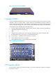
Figure 1 Appearance of the A-F1000-E Firewall A-F5000 The HP A-F5000 firewall (hereinafter referred to as the A-F5000) provides security protection for large enterprises, carriers, and data centers. It adopts multi-core multi-threaded and ASIC processors to construct a distributed architecture, which allows for the separation of the system management and service processing, making it a firewall that has the highest, distributed security processing capability.
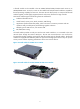
A firewall module can be installed in the HP A5800/A7500/A9500/A12500 Switch Series or an A6608/A8800 router. A switch or router can be installed with multiple firewall modules to expand the firewall processing capability for future use. The main network device (switch or router) and the firewall modules together provide highly integrated network and security functions for large networks.
Figure 5 Firewall module for A6600/A8800 routers Application scenarios The A-F1000-E and A-F5000 have similar software functions. The firewall modules also have similar software functions to the A-F1000-E. You can regard a firewall module as an A-F1000-E firewall that is connected to the main network device through their 10 GE ports.
Figure 6 Network diagram for the A-F1000-E application A-F5000 application Large data centers are connected to the 10G core network usually through a 10G Ethernet. The A-F5000 firewall has a 10G processing capability and abundant port features. It can be deployed at the egress of a network to protect security for the internal network. You can deploy two firewalls to implement stateful failover. • Active-active stateful failover can balance user data.
Firewall module application Firewall modules work with the main network devices (such as A5800/A7500/A9500/A12500 switches and A6600/A8800 routers). Deployed at the egress of a network, the firewall modules can protect against external attacks and implement security access control of the internal network by using security zones. You can meet the development of the network simply by installing more firewall modules to a switch or router.
Login methods Login methods HP Series High-End Firewalls support the following login methods: • Local login through the console port • Remote login through an Ethernet port or through Telnet/SSH • Remote login through the AUX port • Login through the web interface • NMS login In addition to these login methods, HP firewall modules also support login from the network device (a switch or router) that accommodates the firewall module.
Login method Logging in through the AUX port Default state By default, you cannot log in to a device through the AUX port. To do so, log in to the device through the console port, and complete the following configuration: • Configure the password for the default password authentication mode, or change the authentication mode and configure parameters for the new authentication mode. The default user privilege level of AUX login users is 0.
• Local/Remote configuration through Telnet or SSH The methods correspond to the following user interfaces. • Console user interface: Used to manage and monitor users that log in via the console port. The type of the console port is EIA/TIA-232 DCE. • AUX user interface: Used to manage and monitor users that log in via the AUX port. The type of the AUX port is EIA/TIA-232 DTE. The port is usually used for modem dialup access.
CLI login Overview The CLI enables you to interact with a device by typing text commands. At the CLI, you can instruct your device to perform a given task by typing a text command and then pressing Enter to submit it to your device. Compared with the graphical user interface (GUI) where you can use a mouse to perform configuration, the CLI allows you to input more information in one command line. You can log in to the device at the CLI through the console port, Telnet, SSH, or modem.
Setting Default Data bits 8 Login procedure 1. As shown in Figure 9, use the console cable shipped with the device to connect the PC and the device. Plug the DB-9 connector of the console cable into the serial port of the PC, and plug the RJ-45 connector into the console port of your device. Figure 9 Connect the device and PC through a console cable WARNING! Identify interfaces correctly to avoid connection errors. NOTE: The serial port of a PC does not support hot-swap.
Figure 10 Connection description Figure 11 Specify the serial port used to establish the connection 12
Figure 12 Set the properties of the serial port 3. Turn on the device. You are prompted to press Enter if the device successfully completes the power-on self test (POST). A prompt such as appears after you press Enter, as shown in Figure 13. Figure 13 Configuration page 4. Execute commands to configure the device or check the running status of the device. To get help, type ?.
Console login authentication modes The following authentication modes are available for console port login: none, password, and scheme. • none—Requires no username and password at the next login through the console port. This mode is insecure. • password—Requires password authentication at the next login through the console port. Keep your password. • scheme—Requires username and password authentication at the next login through the console port.
Configuring none authentication for console login Configuration prerequisites You have logged in to the device. By default, you can log in to the device through the console port without authentication and have user privilege level 3 after login. For information about logging in to the device with the default configuration, see “Configuration requirements.
Configuring password authentication for console login Configuration prerequisites You have logged in to the device. By default, you can log in to the device through the console port without authentication and have user privilege level 3 after login. For information about logging in to the device with the default configuration, see “Configuration requirements.
Figure 15 Configuration page Configuring scheme authentication for console login Configuration prerequisites You have logged in to the device. By default, you can log in to the device through the console port without authentication and have user privilege level 3 after login. For information about logging in to the device with the default configuration, see “Configuration requirements.
To do… Use the command… Remarks Optional • By default, command authorization is not enabled. • By default, the command level depends on the Enable command authorization user privilege level. A user is authorized a command level not higher than the user privilege level. With command authorization enabled, the command level for a login user is determined by both the user privilege level and AAA authorization.
To do… Use the command… Remarks Specifies the command level of the local user authorization-attribute level level Optional Specify the service type for the local user service-type terminal Configure common settings for console login By default, the command level is 0. Required By default, no service type is specified. Optional — See “Configuring common settings for console login (optional).
To do… Use the command… Remarks Enter system view system-view — Enable display of copyright information copyright-info enable Enter console user interface view user-interface console first-number [ last-number ] Optional Enabled by default. — Optional Configure the baud rate speed speed-value Configure the parity check mode parity { even | mark | none | odd | space } By default, the transmission rate is 9600 bps.
To do… Use the command… Remarks Optional By default, the terminal display type is ANSI. Configure the type of terminal display Configure the user privilege level for login users Set the maximum number of lines on the next screen. Set the size of history command buffer terminal type { ansi | vt100 } The device supports two types of terminal display: ANSI and VT100. HP recommends you to set the display type of both the device and the client to VT100.
Logging in through Telnet Introduction The device supports Telnet. You can telnet to the device to remotely manage and maintain it, as shown in Figure 17. Figure 17 Telnet login The following table shows the configuration requirements of Telnet login. Object Requirements Telnet server Configure the IP address of the management Ethernet interface, and make sure the Telnet server and client can reach each other.( By default, the IP address of the management Ethernet interface is 192.168.0.
Authentication mode None Configuration Remarks Configure not to authenticate users For more information, see “Configuring none authentication for Telnet login.” Configure to authenticate users by using the local password Password Set the local password For more information, see “Configuring password authentication for Telnet login.
To do… Use the command… Remarks Required Configure the command level for login users on the current user interfaces user privilege level level Configure common settings for VTY user interfaces — By default, the default command level is 0 for VTY user interfaces. Optional See “Configuring common settings for VTY user interfaces (optional).” When you log in to the device through Telnet again, perform the following steps: • You enter the VTY user interface, as shown in Figure 18.
To do… Use the command… Remarks Enter one or multiple VTY user interface views user-interface vty first-number [ last-number ] — Required Specify the password authentication mode authentication-mode password Set the local password set authentication password { cipher | simple } password Configure the user privilege level for login users user privilege level level By default, authentication mode for VTY user interfaces is scheme. Required By default, no local password is set.
By default, you can log in to the device through the console port without authentication and have user privilege level 3 after login. For information about logging in to the device with the default configuration, see “Configuration requirements.
To do… Use the command… Remarks Optional • By default, command accounting is disabled. The accounting server does not record the commands executed by users. • Command accounting allows the Enable command accounting command accounting Exit to system view quit Configure the authentic ation mode HWTACACS server to record all executed commands that are supported by the device, regardless of the command execution result. This helps control and monitor user operations on the device.
After you enable command authorization or command accounting, you need to perform the following configuration to make the function take effect: • Create a HWTACACS scheme, and specify the IP address of the authorization server and other authorization parameters. • Reference the created HWTACACS scheme in the ISP domain. When users adopt the scheme mode to log in to the device, the level of the commands that the users can access depends on the user privilege level defined in the AAA scheme.
To do… Use the command… Remarks Required Specify an IP address for the management Ethernet interface ip address ip-address { mask | mask-length } By default, the IP address of the management Ethernet interface is 192.168.0.1/24.
To do… Use the command… Remarks Optional By default, command auto-execution is disabled. Specify a command to be automatically executed when a user logs in to the current user interface auto-execute command command The system automatically executes the specified command when a user logs in to the user interface, and tears down the user connection after the command is executed. If the command triggers another task, the system does not tear down the user connection until the task is completed.
To do… Use the command… Configure the device to log in to a Telnet server as a Telnet client telnet remote-host [ service-port ] [ source { interface interface-type interface-number | ip ip-address } ] telnet ipv6 remote-host [ -i interface-type interface-number ] [ port-number ] Remarks Required Use either command Available in user view Optional Specify the source IPv4 address or source interface for sending Telnet packets telnet client source { interface interface-type interface-number | ip ip-addre
This section includes these topics: • Configuring the SSH server • Configuring the SSH client to log in to the SSH server Configuring the SSH server Configuration prerequisites You have logged in to the device, and want to log in to the device through SSH in the future. By default, you can log in to the device through the console port without authentication and have user privilege level 3 after login.
To do… Use the command… Remarks Optional • By default, command accounting is disabled. The accounting server does not record the commands executed by users. • Command accounting allows Enable command accounting command accounting Exit to system view quit Configure the authentication mode the HWTACACS server to record all executed commands that are supported by the device, regardless of the command execution result. This helps control and monitor user operations on the device.
To do… Use the command… Remarks Create an SSH user, and specify the authentication mode for the SSH user ssh user username service-type stelnet authentication-type { password | { any | password-publickey | publickey } assign publickey keyname } Required Configure common settings for VTY user interfaces — By default, no SSH user exists, and no authentication mode is specified. Optional See “Configuring common settings for VTY user interfaces (optional).
Configuration procedure Follow these steps to configure the SSH client to log in to the SSH server: To do… Use the command… Remarks Required Log in to an IPv4 SSH server ssh2 server server is the IPv4 address or host name of the server. Available in user view Required Log in to an IPv6 SSH server ssh2 ipv6 server server is the IPv6 address or host name of the server. Available in user view NOTE: You can configure other settings for the SSH client to work with the SSH server.
• scheme—Requires username and password authentication at the next login through the AUX port. Authentication falls into local authentication and remote authentication. To use local authentication, configure a local user and related parameters. To use remote authentication, configure the username and password on the remote authentication server. Keep your username and password. The following table lists AUX port login configurations for different authentication modes.
To do… Use the command… Remarks Enter one or more AUX user interface view user-interface aux first-number [ last-number ] — Required Specify the none authentication mode Configure common settings for AUX login authentication-mode none By default, password authentication is performed for users that log in through the AUX port. Optional — See "Configuring common settings for AUX login (optional).
To do… Use the command… Remarks Required Specify the password authentication mode authentication-mode password Set the local password set authentication password { cipher | simple } password By default, you can log in to the device through the AUX port with password authentication and have user privilege level 0 after login. Required By default, no local password is set. Optional Configure common settings for AUX login — See “Configuring common settings for AUX login (optional).
To do… Use the command… Remarks Enter one or more AUX user interface views user-interface aux first-number [ last-number ] — Specify the scheme authentication mode authentication-mode scheme Required By default, the authentication mode for users that log in through the AUX port is password. Optional • By default, command authorization is not enabled. • By default, command level for a login user Enable command authorization depends on the user privilege level.
To do… Use the command… Create a local user and enter local user view local-user user-name Set the authentication password for the local user password { cipher | simple } password Specifies the command level of the local user authorization-attribute level level Specify the service type for the local user service-type terminal Configure common settings for AUX login — Remarks Required By default, no local user exists. Required Optional By default, the command level is 0.
Configuring common settings for AUX login (optional) Follow these steps to configure common settings for AUX login: To do… Use the command… Remarks Enter system view system-view — Enable display of copyright information copyright-info enable Enter AUX user interface view user-interface aux 0 Optional Enabled by default. — Optional Configure the baud rate speed speed-value By default, the baud rate is 9600 bps.
To do… Use the command… Remarks Optional By default, the terminal display type is ANSI. Configure the type of terminal display Configure the user privilege level for login users Set the maximum number of lines on the next screen Set the size of history command buffer terminal type { ansi | vt100 } The device supports two types of terminal display: ANSI and VT100. HP recommends you to set the display type of both the device and the client to VT100.
Object Requirements Device Configure the authentication mode. For more information, see “Configuring none authentication for AUX login,” “Configuring password authentication for AUX login,” and “Configuring scheme authentication for AUX login.” Terminal Run the hyper terminal program. Configure the hyper terminal attributes. Login procedure 1. As shown in Figure 28, use the console cable shipped with the device to connect the PC and the device.
Figure 29 Connection description Figure 30 Specify the serial port used to establish the connection 44
Figure 31 Set the properties of the serial port 3. Turn on the device. You are prompted to enter the login password if the device successfully completes the power-on self test (POST). A prompt such as appears after you press Enter, as shown in Figure 32. Figure 32 Configuration page 4. Execute commands to configure the device or check the running status of the device. To get help, type ?.
Logging in through modems Introduction The administrator can use two modems to remotely maintain a switch through its AUX port over the Public Switched Telephone Network (PSTN) when the IP network connection is broken. Configuration requirements By default, no authentication is needed when you log in through modems, and the default user privilege level is 3. To use this method, perform necessary configurations at both the device side and administrator side.
CAUTION: Note the following device settings: • The baud rate of the AUX port is lower than the transmission rate of the modem. Otherwise, packets may be lost. • The parity check mode, stop bits, and data bits of the AUX port adopt the default settings. 3.
Figure 34 Connection Description Figure 35 Enter the phone number 48
Figure 36 Dial the number 6. Character string CONNECT9600 is displayed on the terminal. Then a prompt such as appears when you press Enter. Figure 37 Configuration page 7. Execute commands to configure the device or check the running status of the device. To get help, type ?. NOTE: • To terminate the connection between the PC and device, execute the ATH command on the terminal to terminate the connection between the PC and modem.
Modem login authentication modes The following authentication modes are available for modem dial-in login: none, password, and scheme. • none—Requires no username and password at the next login through modems. This mode is insecure. • password—Requires password authentication at the next login through the console port. Keep your password. If you lose your password, you cannot log in to the device through password authentication.
Configuring none authentication for modem login Configuration prerequisites You have logged in to the device. By default, you can log in to the device through the console port without authentication and have user privilege level 3 after login. For information about logging in to the device with the default configuration, see “Configuration requirements.” When you log in to the device through modems, specify operating mode of the AUX interface is protocol.
Figure 38 Configuration page HP Configuring password authentication for modem login Configuration prerequisites You have logged in to the device. By default, you can log in to the device through the console port without authentication and have user privilege level 3 after login. For information about logging in to the device with the default configuration, see “Configuration requirements.” When you log in to the device through modems, specify operating mode of the AUX interface is protocol.
To do… Use the command… Remarks Optional Configure common settings for VTY user interfaces For more information, see “Configuring common settings for VTY user interfaces (optional).” — After the configuration, when you log in to the device through modems, you are prompted to enter a login password. A prompt such as appears after you input the password and press Enter, as shown in Figure 39.
To do… Use the command… Remarks Exit to system view quit — Enter AUX user interface view user-interface aux first-number [ last-number ] — Required Specify the scheme authentication mode authentication-mode scheme Whether local, RADIUS, or HWTACACS authentication is adopted depends on the configured AAA scheme. By default, the modem login authentication mode is password. Optional • By default, command authorization is not enabled.
To do… Configure the authentica tion mode Use the command… Enter the default ISP domain view domain domain-name Apply the specified AAA scheme to the domain authentication default { hwtacacs-scheme hwtacacs-scheme-name [ local ] | local | none | radius-scheme radius-scheme-name [ local ] } Return to system view quit Create a local user and enter local user view local-user user-name Set the authentication password for the local user password { cipher | simple } password Specifies the command leve
Figure 40 Configuration page Configuring common settings for modem login (optional) Follow these steps to configure common settings for modem login: To do… Use the command… Remarks Enter system view system-view — Enable display of copyright information copyright-info enable Enter one or more AUX user interface views user-interface aux first-number [ last-number ] Optional Enabled by default. — Optional Configure the baud rate speed speed-value By default ,the baud rate is 9600 bps.
To do… Use the command… Remarks Optional By default, the data bits of the AUX port is 8. Configure the data bits databits { 5 | 6 | 7 | 8 } Define a shortcut key for starting a session activation-key character Data bits is the number of bits representing one character. The setting depends on the contexts to be transmitted. For example, you can set it to 7 if standard ASCII characters are to be sent, and set it to 8 if extended ASCII characters are to be sent.
To do… Use the command… Remarks Optional Set the idle-timeout timer idle-timeout minutes [ seconds ] The default idle-timeout is 10 minutes. The system automatically terminates the user’s connection if there is no information interaction between the device and the user within the idle-timeout time. Setting idle-timeout to 0 disables the timer.
To do… Use the command… Remarks Available in user view Release a specified user interface free user-interface { num1 | { aux | vty } num2 } Multiple users can log in to the system to simultaneously configure the device. In some circumstances, when the administrator wants to make configurations without interruption from the users that have logged in through other user interfaces, the administrator can execute the command to release the connections established on the specified user interfaces.
Web login Web login overview The device provides the web-based network management function to facilitate device operation and maintenance. With this function, the administrator can visually manage and maintain network devices through web-based configuration interfaces. Configuration guidelines • The web-based network management function supports the operating systems of Windows XP, Windows 7 and Windows Vista. • The web-based configuration interface supports Microsoft Internet Explorer 6.
3. On the PC, launch the browser, type the IP address 192.168.0.1 in the address bar, and press Enter to enter the web login page, as shown in Figure 41. Enter username admin, password admin, and the verification code, select a language (English), and click Login. Figure 41 Web login page CAUTION: • To get a new verification code, click on the verification code picture. • Up to five users can concurrently log in to the device through the web interface.
• HTTP login—The Hypertext Transfer Protocol (HTTP) is used for transferring web page information across the Internet. It is an application-layer protocol in the TCP/IP protocol suite. The connection-oriented Transport Control Protocol (TCP) is adopted at the transport layer. Currently, the device supports HTTP 1.0. • HTTPS login—The Secure HTTP (HTTPS) refers to the HTTP protocol that supports the Security Socket Layer (SSL) protocol.
To do… Use the command… Remarks Required Specify the Telnet service type for the local user service-type web By default, no service type is configured for the local user. Exit to system view quit — Enter management Ethernet interface view interface interface-type interfac-number Required Assign an IP address and subnet mask to the management Ethernet interface ip address ip-address { mask | mask-length } Required By default, the IP address of the management Ethernet interface is 192.168.0.
To do… Use the command… Remarks Required Disabled by default. Enable the HTTPS service ip https enable Enabling the HTTPS service triggers an SSL handshake negotiation process. During the process, if the local certificate of the device exists, the SSL negotiation succeeds, and the HTTPS service can be started properly. If no local certificate exists, a certificate application process will be triggered by the SSL negotiation.
To do… Use the command… Remarks Required Create a local user and enter local user view local-user user-name Configure a password for the local user password { cipher | simple } password By default, no local user is configured. Required By default, no password is configured for the local user.
Figure 42 Network diagram for configuring HTTP login Configuration procedure 1. Configuration on the device # Log in to the device via the console port and configure the IP address and mask of the management Ethernet interface GigabitEthernet 0/1 of the device. system-view [Firewall] interface GigabitEthernet0/1 [Firewall-GigabitEthernet0/1] ip address 10.153.17.82 255.255.255.0 [Firewall-GigabitEthernet0/1] quit # Create a local user named admin, and set the password to admin for the user.
# Type the user name, password, verify code, select English, and click Login. The homepage appears. After login, you can configure device settings through the web interface. HTTPS login example Network requirements As shown in Figure 44, to prevent unauthorized users from accessing the Device, configure HTTPS login as follows: • Configure the Firewall as the HTTPS server, and request a certificate for it. • The Host acts as the HTTPS client. Request a certificate for it.
[Firewall] public-key local create rsa # Retrieve the CA certificate from the certificate issuing server. [Firewall] pki retrieval-certificate ca domain 1 # Request a local certificate from a CA through SCEP for the Firewall. [Firewall] pki request-certificate domain 1 # Create an SSL server policy myssl, specify PKI domain 1 for the SSL server policy, and enable certificate-based SSL client authentication.
NOTE: • To log in to the web interface through HTTPS, enter the URL address starting with https://. To log in to the web interface through HTTP, enter the URL address starting with http://. • For more information about the SSL commands, see Network Management Command Reference. Troubleshooting web login problems Problem 1: Unable to access the device through web Problem description The user can ping the device successfully, and log in to the device through Telnet.
Figure 45 Internet Explorer setting (I) • Click Custom Level, and a dialog box Security Settings appears. • As shown in Figure 46, select the Enable button for Run ActiveX controls and plug-ins, Script ActiveX controls marked safe for scripting, and Active scripting.
Figure 46 Internet Explorer setting (II) • Click OK in the Security Settings dialog box. Solution for Mozilla Firefox • Open the Firefox Web browser, and then select Tools > Options. • Click the Content tab, select the Enable JavaScript check box, and click OK.
Figure 47 Firefox web browser setting 72
NMS login NMS login overview A Network Management Station (NMS) runs the SNMP client software. It offers a user-friendly interface to facilitate network management. An agent is a program that resides in the device. It receives and handles requests from the NMS. An NMS is a manager in an SNMP enabled network, whereas agents are managed by the NMS. The NMS and agents exchange information through the SNMP protocol. At present, the device supports multiple NMS programs, such as IMC.
Configuring NMS login Connect the Ethernet port of the PC to the management Ethernet interface of the firewall module over an IP network, as shown in Figure 48. Make sure the PC and the firewall module can reach each other. Figure 48 Network diagram for configuring NMS login Follow these steps to configure SNMPv3 settings: To do… Use the command… Remarks Enter system view system-view — Optional Disabled by default.
To do… Use the command… Directly Configure SNMP NMS access right Configure an SNMP community snmp-agent community { read | write } community-name [ acl acl-number ] Configure an SNMP group snmp-agent group { v1 | v2c } group-name [ read-view read-view ] [ write-view write-view ] [ notify-view notify-view ] [ acl acl-number ] Add a user to the SNMP group snmp-agent usm-user { v1 | v2c } user-name group-name [ acl acl-number ] Indirectly Remarks Required Use either approach.
Figure 49 IMC login page Type the username and password, and then click Login. The IMC homepage appears, as shown in Figure 50. Figure 50 IMC homepage Log in to the IMC and configure SNMP settings for the IMC to find the device. After the device is found, you can manage and maintain the device through the IMC. For example, query device information or configure device parameters. The SNMP settings on the IMC must be the same as those configured on the device.
Logging in to the firewall module from the network device NOTE: This chapter describes how to log in to the firewall module from the network device. Other login methods for the firewall module are the same as a firewall. For more information, see the previous chapters.
Monitoring and managing the firewall module on the network device Resetting the system of the firewall module If the operating system of the firewall module works abnormally (for example, the system does not respond), you can reset the system with the following command. This operation is the same as resetting the firewall module by pressing the reset button on the firewall module.
An ACSEI server can register multiple ACSEI clients. ACSEI timers An ACSEI server uses two timers, the clock synchronization timer and the monitoring timer. • The clock synchronization timer is used to periodically trigger the ACSEI server to send clock synchronization advertisements to ACSEI clients. You can set this timer through command lines. • The monitoring timer is used to periodically trigger the ACSEI server to send monitoring requests to ACSEI clients.
To do… Use the command… Remarks Enter system view system-view — Enter interface view interface interface-type interface-number Required Disabled by default. NOTE: Enable the ACSEI client acsei-client enable The Comware platform can run only one ACSEI client, that is, the ACSEI client can be enabled on only one interface at a time. But the ACSEI client on the Comware platform and that on the firewall module can run simultaneously.
Network diagram Figure 51 Network diagram for monitoring and managing the firewall module Configuration procedure The following configuration uses a switch as an example. The configuration on a router is the same. 1. Log in to the firewall module from the network device # Configure the AUX user interface of the firewall module.
Warning: This command may lose the data on the hard disk if the OAP is not being shut down! Continue? [Y/N]:y Reboot OAP by command. The output shows that you can restart the firewall module on the network device. 2. Display the ACSEI server configuration information on the network device.
Basic configuration You can perform the following basic configuration in the web or at the CLI: • System name and user password. Modify the system name and the password of the current user. For more information, see the chapters “Device management configuration” and “User management.” • Service management. Specify whether to enable the services like FTP, telnet, HTTP, and HTTPS, and set port numbers for HTTP and HTTPS. For more information, see Access Control Configuration Guide.
Figure 52 Basic configuration wizard: 1/6 Configuring the system name and user password Click Next on the first page of the basic configuration wizard to enter the basic information configuration page, as shown in Figure 53.
Figure 53 Basic configuration wizard: 2/6 (basic information) Table 2 Basic information configuration items Item Description Sysname Set the system name. Modify Current User Password Specify whether to modify the login password of the current user. New Password Confirm Password To modify the password of the current user, set the new password and the confirm password, and the two passwords must be identical.
Figure 54 Basic configuration wizard: 3/6 (service management) Table 3 Service management configuration items Item FTP Telnet Description Specify whether to enable FTP on the device. Disabled by default. Specify whether to enable telnet on the device. Disabled by default. Specify whether to enable HTTP on the device, and set the HTTP port number. Disabled by default.
Item Description Specify whether to enable HTTPS on the device, and set the HTTPS port number. Disabled by default. IMPORTANT: • If the current user logged in to the web interface through HTTPS, disabling HTTPS HTTPS or modifying the HTTPS port number will result in disconnection with the device; therefore, perform the operation with caution. • When you modify a port number, ensure that the port number is not used by another service. • By default, HTTPS uses the PKI domain default.
Table 4 Interface IP address configuration items Item Description Set the approach for obtaining the IP address, including: • None: The IP address of the interface is not specified, that is, the interface has no IP address. • Static Address: Specify the IP address for the interface IP Configuration manually; if you select this item, you need to specify both the IP address and the mask. • DHCP: The interface obtains an IP address automatically through the DHCP protocol.
Table 5 NAT configuration items Item Description Interface Select an interface on which the NAT configuration will be applied. Specify whether to enable dynamic NAT on the interface. Dynamic NAT If dynamic NAT is enabled, the IP address of the interface will be used as the IP address of a matched packet after the translation. By default, dynamic NAT is disabled. Source IP/Wildcard If dynamic NAT is enabled, set the source IP address and wildcard for packets.
Figure 57 Basic configuration wizard: 6/6 This page lists all configurations you have made in the basic configuration wizard. Confirm the configurations. To modify your configuration, click Prev to go back to the previous page; if no modification is needed, click Finish to execute all configurations.
Device management Device management overview Device management functions enable you to check the operating status and configure the running parameters of devices. Configuring the device name NOTE: You can configure the device name in the web interface or the comand line interface (CLI). Configuring the device name in the web interface The current system name is on the very top of the navigation tree, as shown in Figure 58.
To do… Use the command… Remarks Optional Configure the device name sysname sysname The device name depends on the device model. Configuring the system time NOTE: • The firewall modules synchronize the time with the NTP server (a primary networking device installed with a firewall module) through NTP. The system time resets to 12:00:00, 26, April, 2000 each time it starts, and is synchronized to the correct time after the system starts up.
Configuring the system time Select Device Management > System Time from the navigation tree, and you will enter the System Time tab page, as shown in Figure 60. Click the System Time Configuration text to open a calendar, as shown in Figure 61. Figure 61 Calendar page You can modify the system time either in the System Time Configuration text box, or through the calendar page.
Figure 62 Network time Table 6 Network time configuration items Item Description Clock status Displays the synchronization status of the system clock. Set the IP address of the local clock source to 127.127.1.u, where u ranges from 0 to 3, representing the NTP process ID. Local Reference Source • If the IP address of the local clock source is specified, the local clock is used as the reference clock, and thus can provide time for other devices.
Item Description Set NTP authentication key. The NTP authentication feature should be enabled for a system running NTP in a network where there is a high security demand. This feature enhances the network security by means of client-server key authentication, which prohibits a client from synchronizing with a device that has failed authentication. Key 1 You can set two authentication keys, each of which is composed of a key ID and key string. Key 2 External Reference Source • ID is the ID of a key.
After the above configuration, you can see that the current system time displayed on the System Time page is the same for Device A and Device B. Configuration guidelines • A device can act as a server to synchronize the clock of other devices only after its clock has been synchronized. If the clock of a server has a stratum level higher than or equal to that of a client’s clock, the client will not synchronize its clock to the server’s. • The synchronization process takes a period of time.
The default system time is 2005/1/1 1:00:00 in the example.
Configuration System time configured Example If “date-time” is not in the daylight saving time range, the system time configured is “date-time”.
Configuration System time configured Example “date-time” is in the daylight saving time range: Configure: clock timezone zone-time add 1, clock summer-time ss one-off 1:00 2008/1/1 1:00 2008/8/8 2 and clock datetime 1:30 2008/1/1 If the value of “date-time”-“summer-offset” is not in the summer-time range, the system time configured is “date-time”-“summer-offset”; If the value of “date-time”-“summer-offset” is in the summer-time range, the system time configured is “date-time”.
To do… Use the command… Remarks Enter system view system-view — Enter user interface view user-interface { first-num1 [ last-num1 ] | { aux | console | vty } first-num2 [ last-num2 ] } — Set the idle timeout timer idle-timeout minutes [ seconds ] Required 10 minutes by default Enabling the display of copyright information • When the display of copyright information is enabled, the copyright information appears when a user logs in through Telnet or SSH, or when a user quits user view after loggi
Configuring banners Follow these steps to configure banners: To do… Use the command… Remarks Enter system view system-view — Configure the incoming banner (for Modem login users) header incoming text Optional Configure the login banner header login text Optional Configure the legal banner header legal text Optional Configure the shell banner (for non Modem login users) header shell text Optional Configure the motd banner header motd text Optional The system supports single-line input an
• Method III—Type multiple characters after the command keywords at the first line (with the first and last characters being different), and then press Enter. Type the rest banner information, and finish your setting with the first character you typed at the first line. The first input character at the first line and the end character are not part of the banner information. For example, to configure a banner like “Have a nice day.
Rebooting the firewall Rebooting the firewall in the web interface Select Device Management > Reboot from the navigation tree to enter the page, as shown in Figure 65. Figure 65 Device reboot configuration page Click Apply to reboot the device. If you select Check whether the configuration is saved to the configuration file for next boot, the device will do the related checking before rebooting.
The last two methods are also called hot start, which is mainly used to reboot a device remotely.
Comparison item Configuring a scheduled task—approach 1 Configuring a scheduled task—approach 2 Can multiple scheduled tasks be configured? No Yes No Yes If you use the schedule job command repeatedly, only the last configuration takes effect. You can use the time command in job view to configure commands to be executed at different time points. Supported views User view and system view. In the schedule job command, shell represents user view, and system represents system view. All views.
Configuring a scheduled task—approach 2 Follow these steps to configure a scheduled task: To do… Use the command… Remarks Enter system view system-view — Create a scheduled task and enter job view job job-name Required Specify the view in which the task is executed view view-name You can specify only one view for a task.
Figure 67 Network diagram for scheduled task configuration Firewall Configuration procedure # Enter system view. system-view # Create scheduled task pc1, and enter its view. [Firewall] job pc1 # Configure the task to be executed in the view of GigabitEthernet 0/1. [Firewall-job-pc1] view GigabitEthernet 0/1 # Configure the Firewall to start GigabitEthernet 0/1 at 8:00 on working days every week.
# Configure the Firewall to shut down GigabitEthernet 0/3 at 18:00 on working days every week. [Firewall-job-pc3] time 2 repeating at 18:00 week-day mon tue wed thu fri command shutdown [Firewall-job-pc3] quit # Display information about scheduled tasks.
• Existing interfaces’ indexes remain unchanged. Follow these steps to clear unused 16-bit interface indexes: To do… Use the command… Clear unused 16-bit interface indexes reset unused porttag Remarks Required Available in user view. CAUTION: A confirmation is required when you execute this command. If you fail to make a confirmation within 30 seconds or enter N to cancel the operation, the command will not be executed.
To do… Use the command… Remarks Display part of the electrical label information of the anti-spoofing transceivers customized by HP display transceiver manuinfo interface [ interface-type interface-number ] Available for anti-spoofing pluggable transceivers customized by HP only. NOTE: • A vendor name of HP indicates an HP-customized anti-spoofing transceiver. Use the display transceiver command to verify it.
To do… Use the command… Remarks Display CPU usage history statistics in a chart display cpu-usage history [ task task-id ] Available in any view Display information about a card, CF card or USB display device [ cf-card | usb | verbose ] Available in any view Display the electrical label information display device manuinfo Available in any view Display the temperature information display environment [ cpu ] Available in any view Display fan operating states display fan [ fan-id ] Available i
User management Configuring local users NOTE: The firewall supports configuring local users only in the web interface. Local user overview Local users are a set of user accounts configured on the firewall. A local user is uniquely identified by username. To enable users using a certain network service to pass local authentication, you must add corresponding entries to the local user database on the firewall.
Figure 69 Add a local user Table 10 Local user configuration items Item Description Enter a username. A username is case sensitive, and cannot contain any of these characters: “/”, “\”, “:”, “|”, “*”, “?”, “<”, “>”, “@” and “"”. User Name IMPORTANT: A username may contain spaces. However, leading spaces and trailing spaces are always ignored. An all-space input is considered null. User Privilege Level Set the user privilege level of the user.
• Select User > Local User in the navigation tree and then click Add. • Type telnet as the username. • Select Visitor as the user privilege level. • Select Telnet as the service type. • Type 123456 as the password. • Type 123456 as the confirm password. • Click Apply. Configuring user login control NOTE: The firewall supports configuring user login control only in the command line interface (CLI).
To do… Use the command… Remarks Configure rules for this ACL rule [ rule-id ] { permit | deny } [ source { sour-addr sour-wildcard | any } | time-range time-name | fragment | logging ]* Required Exit the basic ACL view quit — Enter user interface view user-interface [ type ] first-number [ last-number ] — Required Use the ACL to control user login by source IP address acl [ ipv6 ] acl-number { inbound | outbound } inbound: Filters incoming Telnet packets.
To do… Use the command… Remarks Create an Ethernet frame header ACL and enter its view, or enter the view of an existing Ethernet frame header ACL acl number acl-number [ match-order { config | auto } ] Configure rules for the ACL rule [ rule-id ] { permit | deny } rule-string Required Exit the advanced ACL view quit — Enter user interface view user-interface [ type ] first-number [ last-number ] — Use the ACL to control user login by source MAC address acl acl-number inbound Required By def
[Firewall-ui-vty0-4] acl 2000 inbound Configuring source IP-based login control over NMS users Administrators can use a network management station (NMS) to remotely log in and manage the Firewall through the Simple Network Management Protocol (SNMP). By using an ACL, you can control SNMP user access to the Firewall. Configuration preparation Before configuration, determine the permitted or denied source IP addresses. Configuration procedure Basic ACLs match the source IP addresses of packets.
Source IP-based login control over NMS users configuration example Network requirements As shown in Figure 72, configure the Firewall to allow only NMS users from Host A and Host B to access. Figure 72 Network diagram for configuring source IP-based login control over NMS users Configuration procedure # Create ACL 2000, and configure rule 1 to permit packets sourced from Host B, and rule 2 to permit packets sourced from Host A.
To do… Use the command… Remarks Create a basic ACL and enter its view, or enter the view of an existing basic ACL acl [ ipv6 ] number acl-number [ match-order { config | auto } ] Required Create rules for this ACL rule [ rule-id ] { permit | deny } [ source { sour-addr sour-wildcard | any } | time-range time-name | fragment | logging ]* Required Exit the basic ACL view quit — Associate the HTTP service with the ACL ip http acl acl-number Associate the HTTPS service with the ACL ip https acl a
[Firewall] ip http acl 2030 Displaying online users NOTE: The firewall supports configuring user login control only in the web interface. Overview Online users here refer to users getting online after passing AAA authentication. Displaying online users Select User > Online User from the navigation tree. The online user list appears, as shown in Figure 74. This list shows all current online users.
CLI configuration What is CLI? The command line interface (CLI) enables you to interact with your device by typing text commands. At the CLI, you can instruct your device to perform a given task by typing a text command and then pressing Enter. Compared with the graphical user interface (GUI) where you can use a mouse to perform configurations, the CLI allows you to input more information in one command line.
Convention Description { x | y | ... } Alternative items are grouped in braces and separated by vertical bars. One is selected. [ x | y | ... ] Optional alternative items are grouped in square brackets and separated by vertical bars. One or none is selected. { x | y | ... } * Alternative items are grouped in braces and separated by vertical bars. A minimum of one or a maximum of all can be selected. [ x | y | ...
CLI views adopt a hierarchical structure, as shown in Figure 77. • After logging in to the switch, you are in user view. The prompt of user view is . In user view, you can perform display, debugging, and file management operations, set the system time, restart your device, and perform FTP and Telnet operations. • You can enter system view from user view. In system view, you can configure parameters such as daylight saving time, banners, and short-cut keys.
Exiting the current view The CLI is divided into different command views. Each view has a set of specific commands and defines the effective scope of the commands. The commands available to you at any given time depend on the view you are in. Follow the step below to exit the current view: To do… Use the command… Return to the parent view from the current view quit Remarks Required Available in any view.
debugging Send debug information to terminal logging Send log information to terminal monitor Send information output to current terminal trapping Send trap information to terminal If ? is at the position of an argument, the CLI displays a description about this argument.
Key Function If you press Tab after entering part of a keyword, the system automatically completes the keyword: • If finding a unique match, the system substitutes the complete keyword for the incomplete one and displays it in the next line. Tab • If there is more than one match, you can press Tab repeatedly to display in cycles all the keywords starting with the character string that you typed.
To do… Use the command… Remarks Required Enable the command alias function command-alias enable Disabled by default, which means you cannot configure command aliases. Configure a command alias command-alias mapping cmdkey alias Required Not configured by default.
Hotkey Function Ctrl+V Pastes the content in the clipboard. Ctrl+W Deletes all the characters in a continuous string to the left of the cursor. Ctrl+X Deletes all the characters to the left of the cursor. Ctrl+Y Deletes all the characters to the right of the cursor. Ctrl+Z Exits to user view. Ctrl+] Terminates an incoming connection or a redirect connection. Esc+B Moves the cursor to the leading character of the continuous string to the left.
Checking command-line errors If a command contains syntax errors, the CLI reports error information. Table 15 lists some common command line errors. Table 15 Common command line errors Error information Cause % Unrecognized command found at '^' position. The command was not found. % Incomplete command found at '^' position. Incomplete command % Ambiguous command found at '^' position. Ambiguous command Too many parameters Too many parameters % Wrong parameter found at '^' position.
more information about the history-command max-size command, see Getting Started Guide Command Reference.
To do… Use the command… Remarks Required Disable the multi-screen display function By default, a login user uses the settings of the screen-length command. The default settings of the screen-length command are: multiple-screen display is enabled and up to 24 lines are displayed on the next screen. screen-length disable This command is executed in user view, and takes effect for the current user only. When the user re-logs into the switch, the default configuration is restored.
Character Meaning Remarks + Matches the preceding character or character group one or multiple times For example, “zo+” matches “zo” and “zoo”, but not “z”. | Matches the preceding or succeeding character string For example, “def|int” only matches a character string containing “def” or “int”. _ If it is at the beginning or the end of a regular expression, it equals ^ or $. In other cases, it equals comma, space, round bracket, or curly bracket.
Character Meaning Remarks \bcharacter2 Matches character1character2. character1 can be any character except number, letter or underline, and \b equals [^A-Za-z0-9_]. For example, “\ba” matches “-a” with “-“ being character1, and “a” being character2, but it does not match “2a” or “ba”. \Bcharacter Matches a string containing character, and no space is allowed before character. For example, “\Bt” matches “t” in “install”, but not “t” in “big top”. character1\w Matches character1character2.
Destination/Mask Proto Pre 192.168.1.0/24 Direct 0 Cost NextHop Interface 0 192.168.1.42 Vlan999 Configuring user privilege and command levels Introduction To avoid unauthorized access, the switch defines user privilege levels and command levels. User privilege levels correspond to command levels. When a user at a specific privilege level logs in, the user can only use commands at that level, or lower levels.
To do… Use the command… Remarks Enter system view system-view — Enter user interface view user-interface { first-num1 [ last-num1 ] | { aux | console | vty } first-num2 [ last-num2 ] } — Required By default, the authentication mode for VTY and AUX users is password, and no authentication is needed for console and TTY login users.
• If the authentication mode of a user interface is none or password, the user privilege level of users logging into the user interface is the user interface level. Follow these steps to configure the user privilege level under a user interface (SSH publickey authentication type): To do… Use the command… Remarks Required if the SSH login mode is adopted, and only username is needed during authentication.
Example of configuring a user privilege level under a user interface # Perform no authentication on users logged in to the switch through Telnet, and specify their privilege level as 1. (Use no authentication mode in a secure network environment.
To do… Use the command… Remarks Required Switch the user privilege level super [ level ] When logging in to the switch, a user has a user privilege level, which depends on user interface or authentication user level. Available in user view. Modifying the level of a command All the commands in a view default to different levels. The administrator can change the default level of a command to a lower level or a higher level as needed.
Support and other resources Contacting HP For worldwide technical support information, see the HP support website: http://www.hp.
Conventions This section describes the conventions used in this documentation set. Command conventions Convention Description Boldface Bold text represents commands and keywords that you enter literally as shown. Italic Italic text represents arguments that you replace with actual values. [] Square brackets enclose syntax choices (keywords or arguments) that are optional. { x | y | ... } Braces enclose a set of required syntax choices separated by vertical bars, from which you select one.
Network topology icons Represents a generic network device, such as a router, switch, or firewall. Represents a routing-capable device, such as a router or Layer 3 switch. Represents a generic switch, such as a Layer 2 or Layer 3 switch, or a router that supports Layer 2 forwarding and other Layer 2 features. Represents a firewall chassis or a firewall module. Port numbering in examples The port numbers in this document are for illustration only and might be unavailable on your device.
Index ACDEILMNOPRSTUW Example for monitoring and managing the firewall module from the network device,80 A Application scenarios,4 I C Identifying and diagnosing pluggable transceivers,109 Checking command-line errors,129 Clearing unused 16-bit interface indexes,108 L CLI views,122 Logging in through modems,46 Command conventions,121 Logging in through SSH,31 Configuration guidelines,60 Logging in through Telnet,22 Configuring a scheduled task,104 Logging in through the AUX port,35 Configurin
Troubleshooting web login problems,69 Using the CLI online help,124 Typing commands,125 W U Web login example,65 Undo form of a command,122 Web login overview,60 User interface overview,8 What is CLI?,121 Using command history,129 143