HP High-End Firewalls High Availability Command Reference Part number: 5998-2643 Software version: F1000-E/Firewall module: R3166 F5000-A5: R3206 Document version: 6PW101-20120706
Legal and notice information © Copyright 2012 Hewlett-Packard Development Company, L.P. No part of this documentation may be reproduced or transmitted in any form or by any means without prior written consent of Hewlett-Packard Development Company, L.P. The information contained herein is subject to change without notice.
Contents VRRP configuration commands ··································································································································· 1 vrrp mode ·································································································································································· 1 display vrrp ·························································································································································
probe count ···························································································································································· 52 probe packet-interval ············································································································································ 53 probe packet-number ············································································································································ 54 probe pack
Websites································································································································································· 89 Conventions ···································································································································································· 90 Index ························································································································································
VRRP configuration commands NOTE: • The term router in this document refers to both routers and Firewall • At present, the interfaces that VRRP involves can only be Layer 3 Ethernet interfaces, VLAN interfaces, Layer 3 aggregate interfaces unless otherwise specified. • VRRP cannot be configured on an interface of an aggregation group.
display vrrp Syntax display vrrp [ verbose ] [ interface interface-type interface-number [ vrid virtual-router-id ] ] View Any view Default level 1: Monitor level Parameters verbose: Displays detailed state information of VRRP group(s). interface interface-type interface-number: Displays VRRP group state information of the specified interface. interface-type interface-number specifies an interface by its type and number. vrid virtual-router-id: Displays state information of the specified VRRP group.
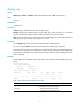
Field Description Current VRRP running mode, including • Real MAC: Real MAC mode, which means the virtual IP address of the VRRP group is mapped to the real MAC address of the interface. Run Method • Virtual MAC: Virtual MAC mode, which means the virtual IP address of the VRRP group is mapped to the virtual MAC address.
Table 2 Output description (standard protocol mode) Field Description Current VRRP working mode, including: Run Mode • Standard: Standard protocol mode • Load Balance: Load balancing mode Current VRRP running mode, including • Real MAC: Real MAC mode, which means the virtual IP Run Method address of the VRRP group is mapped to the real MAC address of the interface. • Virtual MAC: Virtual MAC mode, which means the virtual IP address of the VRRP group is mapped to the virtual MAC address.
Field Description Virtual MAC Virtual MAC address that corresponds to the virtual IP address of the VRRP group. It is displayed only when the router is in the state of master. Master IP Primary IP address of the interface where the router in the state of master resides VRRP Track Information Information about the tracked interface or object. It is displayed only when the vrrp vrid track or vrrp vrid track interface command is executed. Track Interface The interface to be tracked.
Table 3 Output description (load balancing mode) Field Description Current VRRP working mode, including Run Mode • Standard: Standard protocol mode • Load Balance: Load balancing mode Current VRRP running mode, including • Real MAC: Real MAC mode, which means the virtual IP address of the VRRP group is mapped to the real MAC address of the interface. Run Method • Virtual MAC: Virtual MAC mode, which means the virtual IP address of the VRRP group is mapped to the virtual MAC address.
VRID : 1 Adver Timer : 1 Admin Status : Up State : Master Config Pri : 120 Running Pri : 110 Preempt Mode : Yes Delay Time : 5 Auth Type : None Virtual IP : 10.1.1.1 Member IP List : 10.1.1.2 (Local, Master) 10.1.1.
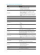
Field Description Adver Timer VRRP advertisement interval, in seconds. Administrative state, including Admin Status • UP • DOWN This field indicates the status of the router in the VRRP group, including: State • Master • Backup • Initialize Config Pri Configured priority of the router, that is, the priority value specified by using the vrrp vrid priority command. Running Pri Running priority of the router, that is, the current priority of the router.
Field Description State of the tracked interface or track entry. The state of a tracked interface includes: State • Up • Down • Removed The state of a track entry includes: • • • • Invalid Negative Positive Not existing Pri Reduced The priority value that is reduced when the monitored interface is down or removed, or when the status of the monitored track entry turns to negative. It is displayed only when the vrrp vrid track interface command or the vrrp vrid track command is executed.
Field Description Weight Reduced The weight value that is reduced when the status of the monitored track entry turns to negative. It is displayed only when the vrrp vrid weight track command is executed. VF switchover information Forwarder Switchover Track Information The information is displayed only after the vrrp vrid track forwarder-switchover command is executed.
Examples # When VRRP works in standard protocol mode, display the statistics about all VRRP groups.
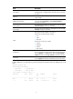
Field Description Version Errors Number of packets with version errors Invalid Type Pkts Rcvd Number of packets with incorrect packet type Advertisement Interval Errors Number of packets with advertisement interval errors IP TTL Errors Number of packets with TTL errors Auth Failures Number of packets with authentication failures Invalid Auth Type Number of packets with authentication failures due to invalid authentication types Auth Type Mismatch Number of packets with authentication failures
Field Description Become Master Number of times that the router worked as the master Redirect Timer Expires Number of times that the redirect timer expires Become AVF Number of times that the VF worked as the AVF Time-out Timer Expires Number of times that the timeout timer expires Advertise Rcvd Number of received advertisements Request Rcvd Number of received requests Advertise Sent Number of advertisements sent Request Sent Number of requests sent Reply Rcvd Number of received replies
If you specify both an interface and a VRRP group, the statistics about the specified VRRP group on the specified interface are cleared. If you specify only the interface, the statistics about all the VRRP groups on the interface are cleared. If you specify neither, the statistics about all the VRRP groups on the router are cleared. Related commands: display vrrp statistics. Examples # Clear the statistics about all the VRRP groups on the router.
undo vrrp method View System view Default level 2: System level Parameters real-mac: Maps the real MAC address of the interface to the virtual IP address of the VRRP group. virtual-mac: Maps the virtual MAC address to the virtual IP address of the VRRP group. Description Use the vrrp method command to specify the type of the MAC addresses mapped to the virtual IP addresses of the VRRP groups. Use the undo vrrp method command to restore the default.
The master of a VRRP group periodically sends VRRP advertisements to indicate its existence. The VRRP advertisements are multicast onto the local network segment and not forwarded by a router, and therefore the packet TTL value will not be changed. When the master of a VRRP group advertises VRRP packets, it sets the packet TTL to 255.
Before executing the command, create a VRRP group on an interface and configure the virtual IP address of the VRRP group. You might configure different authentication modes and authentication keys for the VRRP groups on an interface. However, the members of the same VRRP group must use the same authentication mode and authentication key. Related commands: display vrrp.
Examples # Enable preemption on the router in VRRP group 1, and set the preemption delay to five seconds. system-view [Sysname] interface GigabitEthernet0/1 [Sysname-GigabitEthernet0/1] vrrp vrid 1 virtual-ip 10.1.1.
vrrp vrid timer advertise Syntax vrrp vrid virtual-router-id timer advertise adver-interval undo vrrp vrid virtual-router-id timer advertise View Interface view Default level 2: System level Parameters virtual-router-id: VRRP group number, which ranges from 1 to 255. adver-interval: Interval at which the master in the specified VRRP group sends VRRP advertisements. It ranges from 1 to 255 seconds.
Parameters virtual-router-id: VRRP group number, which ranges from 1 to 255. track track-entry-number: Specifies a track entry to be monitored by its number. track-entry-number ranges from 1 to 1024. reduced priority-reduced: Specifies the value by which the priority decreases. priority-reduced ranges from 1 to 255 and defaults to 10. switchover: Specifies the router switchover mode.
View Interface view Default level 2: System level Parameters virtual-router-id: VRRP group number, which ranges from 1 to 255. interface interface-type interface-number: Specifies an interface to be tracked by its type and number. reduced priority-reduced: Value by which the priority decrements. priority-reduced ranges from 1 to 255 and defaults to 10. Description Use the vrrp vrid track interface command to configure to track the specified interface.
undo vrrp vrid virtual-router-id [ virtual-ip virtual-address ] View Interface view Default level 2: System level Parameters virtual-router-id: VRRP group number, which ranges from 1 to 255. virtual-address: Virtual IP address. Description Use the vrrp vrid virtual-ip command to create a VRRP group, and configure a virtual IP address for it, or, add another virtual IP address for an existing VRRP group.
Parameters virtual-router-id: VRRP group number, which ranges from 1 to 255. track track-entry-number: Specifies a track entry to be monitored by its number. track-entry-number ranges from 1 to 1024. reduced weight-reduced: Specifies the value by which the weight decreases. priority-reduced ranges from 1 to 255 and defaults to 30. Description Use the vrrp vrid weight track command to specify the track entry to be monitored by VFs when VRRP works in load balancing mode.
Track configuration commands display track Syntax display track { track-entry-number | all } View Any view Default level 1: Monitor level Parameters track-entry-number: Displays information about the specified track entry, which is in the range 1 to 1024. all: Displays information about all the track entries. Description Use the display track command to display track entry information. Examples # Display information about all track entries.
Field Description Status of a track entry: Status notify 13 seconds later • Positive: The track entry is normal. • Invalid: The track entry is invalid. • Negative: The track entry is abnormal. The track module notifies the application modules of the track entry change 13 seconds later. The information is not displayed after the track module notifies the application modules.
reaction item-num: Specifies the reaction entry to be associated with the track entry. item-num is the reaction entry ID, in the range 1 to 10. delay: Specifies that the track module notifies the application modules of the track entry status change after a specified delay time. If this keyword is not provided, the track module notifies the application modules immediately when the track entry status changes.
delay: Specifies that the track module notifies the application modules of the track entry status change after a specified delay time. If this keyword is not provided, the track module notifies the application modules immediately when the track entry status changes. negative negative-time: Specifies the delay time for the track module to notify the application modules that the status of the track entry changes to Negative. negative-time represents the delay time, ranging from 1 to 300, in seconds.
ipv4: IPv4 protocol status of the interface to be monitored. When the IPv4 protocol status of an interface is up, the status of the track object is Positive; when the IPv4 protocol status of an interface is down, the status of the track object is Negative. You can use the display ip interface brief command to display the IPv4 protocol status of an interface. delay: Specifies that the track module notifies the application modules of the track entry status change after a specified delay time.
NQA configuration commands NQA client configuration commands advantage-factor Syntax advantage-factor factor undo advantage-factor View Voice test type view Default levels 2: System level Parameter factor: Advantage factor, used to count Mean Opinion Scores (MOS) and Calculated Planning Impairment Factor (ICPIF) values. It is in the range 0 to 20. Description Use the advantage-factor command to configure the advantage factor which is used to count MOS and ICPIF values.
View Voice test type view Default level 2: System level Parameters g711a: G.711 A-law codec type. g711u: G.711 μ-law codec type g729a: G.729 A-law codec type. Description Use the codec-type command to configure the codec type for a voice test. Use the undo codec-type command to restore the default. By default, the codec type for a voice test is G.711 A-law. Examples # Configure the codec type for a voice test as g729a.
For example, when the fill data is abcd and the size of the data field of a probe packet is 3 byte, abc is used to fill the packet. When the data field of a probe packet is 6 byte, abcdab is used to fill the packet. • In an ICMP echo test, the configured character string is used to fill the data field in an ICMP echo message.
Test Type Codec type Default value (in bytes) Voice G.729 A-law 32 • For an ICMP echo test, the size of a probe packet is the length of the data field in an ICMP echo message. • For a UDP echo test, UDP jitter test and voice test, the size of a probe packet is the length of the data field in a UDP packet. Examples # Configure the size of an ICMP echo probe packet as 80 bytes.
View DLSw, FTP, DNS, HTTP, ICMP echo, SNMP, TCP, UDP echo, UDP jitter, voice test type view Default level 2: System level Parameters ip-address: Destination IP address of a test operation. Description Use the destination ip command to configure a destination IP address for a test operation. Use the undo destination ip command to remove the configured destination IP address. By default, no destination IP address is configured for a test operation.
display nqa history Syntax display nqa history [ admin-name operation-tag ] View Any view Default level 2: System level Parameters admin-name operation-tag: Displays history records of a test group. If these two arguments are not specified, history records of all test groups are displayed. admin-name represents the name of the administrator who creates the NQA operation. It is a string of 1 to 32 characters, case-insensitive. operation-tag represents the test operation tag.
Field Description Status value of test results, including: • Succeeded • Unknown error Status • Internal error • Timeout Time Time when the test is completed display nqa result Syntax display nqa result [ admin-name operation-tag ] View Any view Default level 2: System level Parameters admin-name operation-tag: Displays results of the last test of a test group. If this argument is not specified, results of the last tests of all test groups are displayed.
Min positive SD: 8 Min positive DS: 8 Max positive SD: 18 Max positive DS: 8 Positive SD number: 5 Positive DS number: 2 Positive SD sum: 75 Positive DS sum: 32 Positive SD average: 15 Positive DS average: 16 Positive SD square sum: 1189 Positive DS square sum: 640 Min negative SD: 8 Min negative DS: 1 Max negative SD: 24 Max negative DS: 30 Negative SD number: 4 Negative DS number: 7 Negative SD sum: 56 Negative DS sum: 99 Negative SD average: 14 Negative DS average: 14 Negative SD sq
Negative SD sum: 0 Negative DS sum: 0 Negative SD average: 0 Negative DS average: 0 Negative SD square sum: 0 Negative DS square sum: 0 One way results: Max SD delay: 0 Max DS delay: 0 Min SD delay: 0 Min DS delay: 0 Number of SD delay: 0 Number of DS delay: 0 Sum of SD delay: 0 Sum of DS delay: 0 Square sum of SD delay: 0 Square sum of DS delay: 0 SD lost packet(s): 0 DS lost packet(s): 0 Lost packet(s) for unknown reason: 1000 Voice scores: MOS value: 0.
Field Description Positive DS sum Sum of positive jitter delays from destination to source Positive SD average Average of positive jitter delays from source to destination Positive DS average Average of positive jitter delays from destination to source Positive SD square sum Square sum of positive jitter delays from source to destination Positive DS square sum Square sum of positive jitter delays from destination to source Min negative SD Minimum absolute value among negative jitter delays from
Field Description Lost packet(s) for unknown reason Number of lost packets for unknown reasons Voice scores Voice parameters, displayed only in a voice test MOS value MOS value calculated for a voice test ICPIF value ICPIF value calculated for a voice test display nqa statistics Syntax display nqa statistics [ admin-name operation-tag ] View Any view Default level 2: System level Parameters admin-name operation-tag: Displays statistics of the specified test group.
Packet(s) arrived late: 0 UDP-jitter results: RTT number: 70 Min positive SD: 1 Min positive DS: 1 Max positive SD: 24 Max positive DS: 22 Positive SD number: 34 Positive DS number: 27 Positive SD sum: 415 Positive DS sum: 362 Positive SD average: 12 Positive DS average: 13 Positive SD square sum: 6593 Positive DS square sum: 6450 Min negative SD: 1 Min negative DS: 1 Max negative SD: 40 Max negative DS: 64 Negative SD number: 28 Negative DS number: 35 Negative SD sum: 28 Negative DS sum:
Positive SD average: 0 Positive DS average: 0 Positive SD square sum: 0 Positive DS square sum: 0 Min negative SD: 0 Min negative DS: 0 Max negative SD: 0 Max negative DS: 0 Negative SD number: 0 Negative DS number: 0 Negative SD sum: 0 Negative DS sum: 0 Negative SD average: 0 Negative DS average: 0 Negative SD square sum: 0 Negative DS square sum: 0 One way results: Max SD delay: 0 Max DS delay: 0 Min SD delay: 0 Min DS delay: 0 Number of SD delay: 0 Number of DS delay: 0 Sum of SD d
Field Description Min positive DS Minimum positive jitter delay from destination to source Max positive SD Maximum positive jitter delay from source to destination Max positive DS Maximum positive jitter delay from destination to source Positive SD number Number of positive jitter delays from source to destination Positive DS number Number of positive jitter delays from destination to source Positive SD sum Sum of positive jitter delays from source to destination Positive DS sum Sum of positi
Field Description Square sum of SD delay Square sum of delays from source to destination Square sum of DS delay Square sum of delays from destination to source SD lost packet(s) Number of lost packets from the source to the destination DS lost packet(s) Number of lost packets from the destination to the source Lost packet(s) for unknown reason Number of lost packets for unknown reasons Voice scores Voice parameters, displayed only in a voice test filename Syntax filename filename undo filename
Default level 2: System level Parameters interval: Interval between two consecutive tests, in milliseconds, in the range 0 to 604800000. If the interval is 0, it indicates that only one test is performed, and no statistics are generated. Description Use the frequency command to configure the interval between two consecutive tests for a test group. Use the undo frequency command to restore the default.
Examples # Enable the history records saving function of an NQA test group. system-view [Sysname] nqa entry admin test [Sysname-nqa-admin-test] type icmp-echo [Sysname-nqa-admin-test-icmp-echo] history-record enable history-record keep-time Syntax history-record keep-time keep-time undo history-record keep-time View Any NQA test type view Default level 2: System level Parameters keep-time: Specifies how long the history records can be saved. The time ranges from 1 to 1440 minutes.
Parameters number: Maximum number of history records that can be saved in a test group, in the range 0 to 50. Description Use the history-record number command to configure the maximum number of history records that can be saved in a test group. Use the undo history-record number command to restore the default. By default, the maximum number of records that can be saved in a test group is 50.
next-hop Syntax next-hop ip-address undo next-hop View ICMP echo test type view Default level 2: System level Parameters ip-address: IP address of the next hop. Description Use the next-hop command to configure the next hop IP address for an IP packet. Use the undo next-hop command to remove the configured next hop IP address. By default, no next hop IP address is configured. Examples # Configure the next hop IP address as 10.1.1.1.
Use the undo nqa command to remove the test group. If the test type has been configured for the test group, you will directly enter NQA test type view when you execute the nqa command. Examples # Create an NQA test group whose administrator name is admin and whose operation tag is test and enter NQA test group view.
Parameters number: Maximum number of the tests that the NQA client can simultaneously perform. The value ranges from 1 to 5. Description Use the nqa agent max-concurrent command to configure the maximum number of tests that the NQA client can simultaneously perform. Use the undo nqa agent max-concurrent command to restore the default. By default, the maximum number of tests that the NQA client can simultaneously perform is 2.
• It is not allowed to enter test group view or test type view after a test group is scheduled. • A test group performs a test when the system time is between the start time and the end time (the start time plus test duration).
View HTTP test type view Default level 2: System level Parameters get: Obtains data from the HTTP server. post: Transfers data to the HTTP server. Description Use the operation command to configure the HTTP operation type. Use the undo operation command to restore the default. By default, the HTTP operation type is get. Examples # Configure the HTTP operation type as post.
[Sysname-nqa-admin-test-dhcp] operation interface gigabitethernet 0/1 password (FTP test type view) Syntax password password undo password View FTP test type view Default level 2: System level Parameters password: Password used to log onto the FTP server, a string of 1 to 32 characters. It is case sensitive. Description Use the password command to configure a password used to log onto the FTP server. Use the undo password command to remove the configured password.
• For a TCP or DLSw test, one probe means one connection; • For a UDP jitter test or a voice test, the number of packets sent in one probe depends on the probe packet-number command; • For an FTP, HTTP, DHCP or DNS test, one probe means to carry out a corresponding function; • For an ICMP echo or UDP echo test, one packet is sent in one probe; • For an SNMP test, three packets are sent in a probe.
probe packet-number Syntax probe packet-number packet-number undo probe packet-number View UDP jitter, voice test type view Default level 2: System level Parameters packet-number: Number of packets sent in a UDP jitter probe or a voice probe. For a UDP jitter test, it is in the range 10 to 1000; for a voice test, it is in the range 10 to 60000. Description Use the probe packet-number command to configure the number of packets sent in a UDP jitter probe or a voice probe.
By default, the timeout time in a UDP jitter and a voice test is 3000 and 5000 milliseconds respectively. Examples # Configure the timeout time for waiting for responses in a UDP jitter test as 100 milliseconds.
Default level 2: System level Parameters item-num: Number of the reaction entry, in the range 1 to 10. checked-element: Type of the monitored element in collaboration. The type of the monitored element can be probe failure only. probe-fail: The type of the monitored element is probe failure. threshold-type consecutive: Threshold type is consecutive probe failures. occurrences: Number of consecutive probe failures, in the range 1 to 16. action-type: Triggered action type, defaulting to none.
Default level 2: System level Parameters probe-failure consecutive-probe-failures: Specifies to send a trap indicating a probe failure to the network management server after consecutive probe failures in an NQA test. consecutive-probe-failures is the number of consecutive probe failures in a test, in the range 1 to 15. test-complete: Specifies to send a trap to indicate that the test is completed.
By default, no domain name is configured. Examples # Set the domain name for DNS resolution to domain1.
Default level 2: System level Parameters interface-type interface-number: Interface type and the interface number of the source interface of a probe packet. Description Use the source interface command to specify the IP address of an interface as the source IP address of ICMP echo probe requests. Use the undo source interface command to remove the IP address of an interface as the source IP address of ICMP echo probe requests.
• For an ICMP echo test, if no source IP address is specified, but the source interface is specified, the IP address of the source interface is taken as the source IP address of ICMP probe requests. • The source IP address specified by the source ip command must be the IP address of an interface on the device, and the interface must be up; otherwise, the test fails. Related commands: source interface. Examples # Configure the source IP address of an ICMP echo probe request as 10.1.1.1.
Default levels 2: System level Parameters hold-time: Hold time of a statistics group in minutes, in the range 1 to 1440. Description Use the statistics hold-time command to configure the hold time of a statistics group. Use the undo statistics hold-time command to restore the default. By default, the hold time of a statistics group is 120 minutes. A statistics group has the aging mechanism.
system-view [Sysname] nqa entry admin test [Sysname-nqa-admin-test] type icmp-echo [Sysname-nqa-admin-test-icmp-echo] statistics max-group 5 statistics interval Syntax statistics interval interval undo statistics interval View DLSw, DNS, FTP, HTTP, ICMP echo, SNMP, TCP, UDP echo, UDP jitter, voice test type view Default levels 2: System level Parameters interval: Interval for collecting statistics of the test results in minutes, in the range 1 to 35791394.
Parameters value: Value of the ToS field in the IP header in an NQA probe packet, in the range 0 to 255. Description Use the tos command to configure the value of the ToS field in the IP header in an NQA probe packet. Use the undo tos command to restore the default. By default, the ToS field in the IP header of an NQA probe packet is 0. Examples # Configure the ToS field in a IP packet header in an NQA probe packet as 1.
View NQA test group view Default level 2: System level Parameters dhcp: DHCP test. dlsw: DLSw test. dns: DNS test. ftp: FTP test. http: HTTP test. icmp-echo: ICMP echo test. snmp: SNMP test. tcp: TCP test. udp-echo: UDP echo test. udp-jitter: UDP jitter test. voice: Voice test. Description Use the type command to configure the test type of the current test group and enter test type view. By default, no test type is configured.
Description Use the url command to configure the website an HTTP test visits. Use the undo url command to remove the configured website an HTTP test visits. The character string of the configured URL cannot contain spaces. Examples # Configure the website that an HTTP test visits as /index.htm. system-view [Sysname] nqa entry admin test [Sysname-nqa-admin-test] type http [Sysname-nqa-admin-test-http] url /index.
Default level 2: System level Parameters instance: VPN instance name, a string of 1 to 31 characters. It is case sensitive. Description Use the vpn-instance command to specify a VPN instance. Use the undo vpn-instance command to restore the default. By default, no VPN instance is specified. After you specify a VPN instance, NQA will test the connectivity of the specified VPN tunnel. Examples # Specify the VPN instance vpn1.
udp-echo: IP Address Port Status 3.3.3.3 3000 inactive Table 12 Output description Field Description tcp-connect NQA server status in the NQA TCP test udp-echo NQA server status in the NQA UDP test IP Address IP address specified for the TCP/UDP listening service on the NQA server Port Port number of the TCP/UDP listening service on the NQA server Listening service status: Status active: Listening service is ready; inactive: Listening service is not ready.
View System view Default level 2: System level Parameters ip-address: IP address specified for the TCP listening service on the NQA server. port-number: Port number specified for the TCP listening service on the NQA server, in the range 1 to 50000.- Description Use the nqa-server tcp-connect command to create a TCP listening service on the NQA server. Use the undo nqa-server tcp-connect command to remove the TCP listening service created. • Configure the command on the NQA server for TCP tests only.
• The IP address and port number must be consistent with those configured on the NQA client and must be different from those of an existing listening service. • The IP address must be that of an interface on the NQA server. Otherwise, the configuration will be invalid. Related commands: nqa server enable, display nqa server status. Examples # Create a UDP listening service by using the IP address 169.254.10.2 and port 9000. system-view [Sysname] nqa server udp-echo 169.254.10.
Ethernet Link Aggregation Configuration Commands Ethernet Link Aggregation Configuration Commands NOTE: Only the A-F5000 supports link aggregation, and only supports static mode. description Syntax description text undo description View Layer 2 aggregate interface view, Layer 3 aggregate interface view, Layer 3 aggregate subinterface view Default Level 2: System level Parameters text: Description of the interface, a string of 1 to 80 characters.
View Any view Default Level 1: Monitor level Parameters None Description Use the display lacp system-id command to display the system ID of the local system. The system ID comprises the system LACP priority and the system MAC address. You can use the lacp system-priority command to change the LACP priority of the local system. When you do that, the LACP priority value you specify in the command is in decimal format. However, it is displayed as a hexadecimal value with the display lacp system-id command.
Description Use the display link-aggregation load-sharing mode command to display global or group-specific link-aggregation load sharing criterion or criteria. Note that: • To display the global link-aggregation load sharing criterion or criteria, run the command without the interface keyword. • To display all the group-specific load sharing criteria, run the command with the interface keyword but do not specify a particular interface.
display link-aggregation load-sharing mode interface Bridge-Aggregation10 Load-Sharing Mode: destination-ip address, source-ip address Route-Aggregation1 Load-Sharing Mode: Layer 2 traffic: destination-ip address, destination-port, source-ip address, source-port, ip-protocol Layer 3 traffic: destination-ip address, destination-port, source-ip address, source-port, ip-protocol Route-Aggregation10 Load-Sharing Mode: destination-ip address, source-ip address Table 14 display link-aggregatio
View Any view Default Level 1: Monitor level Parameters interface-list: Link aggregation member port list, in the form of interface-type interface-number [ to interface-type interface-number ], where interface-type interface-number indicates port type and port number. Description Use the display link-aggregation member-port command to display the detailed link aggregation information on the specified member port(s) or all member ports if no interface is specified.
Oper-Key: 2 Flag: {ACDEF} Received LACP Packets: 5 packet(s) Illegal: 0 packet(s) Sent LACP Packets: 7 packet(s) Table 15 display link-aggregation member-port command output description Field Description One-byte LACP state flags field. From the least to the most significant bit, they are represented by A through H as follows: • A indicates whether LACP is enabled. 1 for enabled and 0 for disabled. • B indicates the timeout control value. 1 for short timeout, and 0 for long timeout.
View Any view Default Level 1: Monitor level Parameters None Description Use the display link-aggregation summary command to display the summary information of all aggregation groups. You may find that information about the remote system for a static link aggregation group is either displayed as none or not displayed at all. This is normal because this type of aggregation group is not aware of its partner. Examples # Display the summary information of all aggregation groups.
Field Description Partner ID System ID of the partner, which comprises the system LACP priority and the system MAC address Select Ports Total number of selected ports Unselect Ports Total number of unselected ports Share Type Load sharing type display link-aggregation verbose Syntax display link-aggregation verbose [ { bridge-aggregation | route-aggregation } [ interface-number ] ] View Any view Default Level 1: Monitor level Parameters bridge-aggregation: Displays detailed information about th
Port Status: S -- Selected, Flags: U -- Unselected A -- LACP_Activity, B -- LACP_Timeout, C -- Aggregation, D -- Synchronization, E -- Collecting, F -- Distributing, G -- Defaulted, H -- Expired Aggregation Interface: Bridge-Aggregation10 Aggregation Mode: Dynamic Loadsharing Type: Shar System ID: 0x8000, 000f-e267-6c6a Local: Port Status Priority Oper-Key Flag ------------------------------------------------------------------------------GE0/2 S 32768 2 {ACDEF} GE0/3 S 32768 2 {ACDEF} Remot
Field Description Aggregation Mode Mode of the aggregation group: Static for static aggregation, and Dynamic for dynamic aggregation. System ID Local system ID, which comprises the system LACP priority and the system MAC address.
Examples # Enable linkUp/linkDown trap generation on Layer 2 aggregate interface Bridge-Aggregation 1. system-view [Sysname] snmp-agent trap enable [Sysname] interface bridge-aggregation 1 [Sysname-Bridge-Aggregation1] enable snmp trap updown interface bridge-aggregation Syntax interface bridge-aggregation interface-number undo interface bridge-aggregation interface-number View System view Default Level 2: System level Parameters interface-number: Layer 2 aggregate interface number.
Parameters interface-number: Layer 3 aggregate interface number. interface-number.subnumber: Sub-interface of a Layer 3 aggregate interface. The interface-number argument specifies the main interface number. The subnumber argument specifies the subinterface number and is separated from the main interface number by a dot (.). Description Use the interface route-aggregation command to create a Layer 3 aggregate interface/subinterface and enter the Layer 3 aggregate interface/subinterface view.
[Sysname] lacp system-priority 64 link-aggregation load-sharing mode Syntax link-aggregation load-sharing mode { destination-ip | destination-port | ip-protocol | source-ip | source-port } * undo link-aggregation load-sharing mode View System view, Layer 2 aggregate interface view, Layer 3 aggregate interface view Default Level 2: System level Parameters destination-ip: Specifies to perform load sharing in link aggregation groups based on destination IP address.
undo link-aggregation mode View Layer 2 aggregate interface view, Layer 3 aggregate interface view Default Level 2: System level Parameters None Description Use the link-aggregation mode dynamic command to configure an aggregation group to work in dynamic aggregation mode. Use the undo link-aggregation mode command to restore the default. By default, an aggregation group works in static aggregation mode.
[Sysname] interface gigabitethernet 0/1 [Sysname-GigabitEthernet0/1] link-aggregation port-priority 64 link-aggregation selected-port maximum Syntax link-aggregation selected-port maximum number undo link-aggregation selected-port maximum View Layer 2 aggregate interface view, Layer 3 aggregate interface view Default Level 2: System level Parameters number: Maximum number of selected ports allowed in the current aggregation group, which is in the range 1 to 8.
Parameters number: Minimum number of selected ports in the current aggregation group required to bring up the aggregate interface, which is in the range 1 to 8. Description Use the link-aggregation selected-port minimum command to configure the minimum number of selected ports in the current aggregation group. Use the undo link-aggregation selected-port minimum command to restore the default. By default, the minimum number of selected ports in an aggregation group is not specified.
port link-aggregation group Syntax port link-aggregation group number undo port link-aggregation group View Ethernet interface view Default Level 2: System level Parameters number: Number of the aggregate interface corresponding to an aggregation group. Description Use the port link-aggregation group command to assign the current Ethernet interface to the specified aggregation group.
route-aggregation: Clears statistics for Layer 3 aggregate interfaces. interface-number: Aggregate interface number. If the interface-number argument is not specified, this command clears statistics of all aggregate interfaces of the specified type. Description Use the reset counters interface command to clear the statistics of the specified aggregate interface or interfaces.
shutdown Syntax shutdown undo shutdown View Layer 2 aggregate interface view, Layer 3 aggregate interface view, Layer 3 aggregate subinterface view Default Level 2: System level Parameters None Description Use the shutdown command to shut down the current aggregate interface/subinterface. Use the undo shutdown command to bring up the current aggregate interface/subinterface. By default, aggregate interfaces/subinterfaces are up.
Support and other resources Contacting HP For worldwide technical support information, see the HP support website: http://www.hp.
Conventions This section describes the conventions used in this documentation set. Command conventions Convention Description Boldface Bold text represents commands and keywords that you enter literally as shown. Italic Italic text represents arguments that you replace with actual values. [] Square brackets enclose syntax choices (keywords or arguments) that are optional. { x | y | ... } Braces enclose a set of required syntax choices separated by vertical bars, from which you select one.
Network topology icons Represents a generic network device, such as a router, switch, or firewall. Represents a routing-capable device, such as a router or Layer 3 switch. Represents a generic switch, such as a Layer 2 or Layer 3 switch, or a router that supports Layer 2 forwarding and other Layer 2 features. Represents a firewall chassis or a firewall module. Port numbering in examples The port numbers in this document are for illustration only and might be unavailable on your device.
Index ACDEFHILMNOPRSTUVW interface bridge-aggregation,80 A interface route-aggregation,80 advantage-factor,29 L C lacp system-priority,81 codec-type,29 link-aggregation load-sharing mode,82 D link-aggregation mode,82 data-fill,30 link-aggregation port-priority,83 data-size,31 link-aggregation selected-port maximum,84 description,70 link-aggregation selected-port minimum,84 description (any NQA test type view),32 M destination ip,32 mtu,85 destination port,33 display lacp system-id,70 N
reset counters interface,86 U reset lacp statistics,87 url,64 reset vrrp statistics,13 username (FTP test type view),65 resolve-target,57 V route-option bypass-route,58 vpn-instance (ICMP echo test type view),65 S vrrp dot1q,14 shutdown,88 vrrp method,14 source interface,58 vrrp mode,1 source ip,59 vrrp un-check ttl,15 source port,60 vrrp vrid authentication-mode,16 statistics hold-time,60 vrrp vrid preempt-mode,17 statistics interval,62 vrrp vrid priority,18 statistics max-group,61