HP High-End Firewalls High Availability Configuration Guide Part number: 5998-2633 Software version: F1000-E/Firewall module: R3166 F5000-A5: R3206 Document version: 6PW101-20120706
Legal and notice information © Copyright 2012 Hewlett-Packard Development Company, L.P. No part of this documentation may be reproduced or transmitted in any form or by any means without prior written consent of Hewlett-Packard Development Company, L.P. The information contained herein is subject to change without notice.
Contents VRRP configuration ······················································································································································· 1 VRRP overview ··································································································································································· 1 Introduction to VRRP ·································································································································
Track configuration task list··········································································································································· 44 Associating the track module with a detection module ····························································································· 44 Associating track with NQA ································································································································ 44 Associating track with interfac
DLSw test configuration example ························································································································· 94 NQA collaboration configuration example········································································································ 95 Ethernet Link Aggregation Configuration ················································································································· 98 Overview··········································
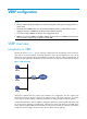
VRRP configuration NOTE: • The term router in this document refers to a network routing device routing an IP routing protocol in a generic sense. • The interfaces that VRRP involves can only be Layer 3 Ethernet interfaces, VLAN interfaces, Layer 3 aggregate interfaces, and RPR logical interfaces unless otherwise specified. • You cannot configure VRRP on an interface of an aggregation group. • VRRP has two versions: VRRPv2 and VRRPv3. VRRPv2 is based on IPv4, and VRRPv3 is based on IPv6.
VRRP is an error-tolerant protocol, which improves the network reliability and simplifies configurations on hosts. Deploying VRRP on multicast and broadcast LANs such as Ethernet, you can ensure that the system can still provide highly reliable default links without changing configurations (such as dynamic routing protocols, route discovery protocols) when a device fails, and prevent network interruption due to failure of a single link.
VRRP priority VRRP determines the role (master or backup) of each router in the VRRP group by priority. A router with a higher priority has more opportunity to become the master. VRRP priority is in the range of 0 to 255. A bigger number means a higher priority. Priorities 1 to 254 are configurable. Priority 0 is reserved for special uses and priority 255 for the IP address owner. When a router acts as the IP address owner, its running priority is always 255.
VRRP preemption delay timer In an unstable network, a backup can fail to receive the packets from the master due to network congestion and thus the members in the group change their states frequently. Set the VRRP preemption delay timer to address the problem. With the VRRP preemption delay timer set, if a backup receives no advertisement in a period three times the advertisement interval and then the preemption delay, it considers that the master fails.
Principles of VRRP • With VRRP enabled, the routers decide their respective roles in the VRRP group by priority. The router with the highest priority becomes the master, and the others are the backups. The master sends VRRP advertisements periodically to notify the backups that it is working properly, and each of the backups starts a timer to wait for advertisements from the master.
Figure 4 VRRP in master/backup mode At the beginning, Router A is the master and therefore can forward packets to external networks, whereas Router B and Router C are backups and are thus in the state of listening. If Router A fails, Router B and Router C elect for a new master. The new master takes over the forwarding task to provide services to hosts on the LAN.
In Figure 5, three VRRP groups are present: • VRRP group 1: Router A is the master; Router B and Router C are the backups. • VRRP group 2: Router B is the master; Router A and Router C are the backups. • VRRP group 3: Router C is the master; Router A and Router B are the backups. To balance load among Router A, Router B, and Router C, configure hosts on the LAN to use VRRP group 1, 2, and 3 as the default gateways respectively.
Figure 7 VRRP group page Figure 8 Create a VRRP group Table 2 VRRP group configuration items Item Description VRID Set the group number of the VRRP group. Configure the virtual IP address of the VRRP group. • If the VRRP interface connects to multiple subnets, you can configure multiple virtual IP addresses for the VRRP group to implement router backup on different subnets. Virtual IP • The virtual IP address cannot be all 0s (0.0.0.0), a broadcast address (255.255.255.
Configuring a VRRP group Select High Reliability > VRRP from the navigation tree to enter the VRRP interfaces page, as shown in Figure 6. Click the icon corresponding to the interface to be configured to enter the VRRP Configuration on Interface page, as shown in Figure 7. Click the icon corresponding to the VRRP group to be configured to enter the Modify VRRP Group page, as shown in Figure 9.
Item Description Set the priority of the routers in a VRRP group. The greater the value, the higher the priority. IMPORTANT: • VRRP determines the role (master or backup) of each router in the VRRP group by Priority priority. A router with a higher priority has more opportunity to become the master. • VRRP priority is in the range of 0 to 255. Priority 0 is reserved for special uses and priority 255 for the IP address owner. • When a router acts as the IP address owner, its priority is always 255.
Table 5 Configuration items of the VRRP group tracking function Item Description Object Configure the track object function: add the Track object to be monitored and the processing method. • Object: Specify the serial number of the Track object to be monitored. You can specify an uncreated object. Reduced Priority • Reduced Priority: If the status of the monitored Track object changes to negative, the priority of the router decreases by a specified value.
• Firewall A and Firewall B belong to VRRP group 1 with the virtual IP address of 202.38.160.111/24. • If Firewall A operates normally, packets sent from Host A to Host B are forwarded by Firewall A; if GigabitEthernet 0/2 connecting Firewall A with the Internet becomes unavailable, packets sent from Host A to Host B are forwarded by Firewall B. Figure 10 Network diagram for single VRRP group configuration Configuration procedure Configure Firewall A # Configure the IP address of GigabitEthernet 0/1.
• Type 5 in the Advertise Time box. • Click Display Track Config. • Select GigabitEthernet0/2 from the Interface box. • Type 30 in the Reduced Priority box. • Click Add to add the interface to the list box of tracked interface. • Click Apply. Configure Firewall B # Configure the IP address of GigabitEthernet 0/1. • Select Device Management > Interface from the navigation tree, and click the corresponding to GigabitEthernet 0/1. • Select the Static Address option. • Type 202.38.160.
Figure 11 Network diagram for multiple VRRP groups configuration Configuration procedure Configure Firewall A # Configure the IP address of GigabitEthernet 0/1. • Select Device Management > Interface from the navigation tree, and click the corresponding to GigabitEthernet 0/1. • Select the Static Address option. • Type 202.38.160.1 in the IP Address box. • Select 24 (255.255.255.0) from the Mask box. • Click Apply. icon # Create VRRP group 1.
• Type 110 in the Priority box. • Click Apply. Configure Firewall B # Configure the IP address of GigabitEthernet 0/1. • Select Device Management > Interface from the navigation tree, and click the corresponding to GigabitEthernet 0/1. • Select the Static Address option. • Type 202.38.160.2 in the IP Address box. • Select 24 (255.255.255.0) from the Mask box. • Click Apply. icon # Create VRRP group 1.
Task Remarks Specifying the VRRP control VLAN Optional Creating a VRRP group and configuring virtual IP address Required Configuring router priority, preemptive mode and tracking function Optional Optional Configuring VF tracking The VF tracking function is effective only when VRRP works in load balancing mode.
virtual MAC address. When such a mapping is adopted, the hosts in the internal network do not need to update the mapping between the IP address and MAC address when the master changes. • Real MAC address of an interface—In case that an IP address owner exists in a VRRP group, if the virtual IP address is mapped to the virtual MAC address, two MAC addresses are mapped to one IP address.
Figure 12 VRRP control VLAN As shown in Figure 12, configure ambiguous VLAN termination for VLAN 10 and VLAN 20 on the Layer 3 Ethernet subinterfaces on routers. To ensure that the master can periodically multicast VRRP advertisements to the backups, be sure to enable the subinterfaces configured with VLAN termination to transmit broadcast/multicast packets. Then, the master sends VRRP advertisements within all VLANs whose VLAN packets are configured to be terminated by the subinterfaces.
To do… Enter interface view Use the command… Layer 3 Ethernet subinterface view interface interface-type interface-number.subnumber Layer 3 aggregation subinterface view interface route-aggregation interface-number.
To do… Use the command… Specify a VRRP control VLAN for the subinterface configured with ambiguous Dot1q termination vrrp dot1q vid vlan-id Specify a VRRP control VLAN for the subinterface configured with ambiguous QinQ termination vrrp dot1q vid vlan-id secondary-dot1q secondary-vlan-id Remarks Required Use either command. By default, no VRRP control VLAN is specified for the subinterface configured with VLAN termination.
NOTE: • The maximum number of VRRP groups on an interface is 255, and the maximum number of virtual IP addresses in a VRRP group is 16. • When VRRP works in standard protocol mode, the virtual IP address of a VRRP group can be either an unused IP address on the segment where the VRRP group resides or the IP address of an interface on a router in the VRRP group. In the latter case, the router is called the IP address owner.
To do… Use the command… Remarks Optional Configure the router in the VRRP group to work in preemptive mode and configure preemption delay vrrp vrid virtual-router-id preempt-mode [ timer delay delay-value ] The router in the VRRP group works in preemptive mode and the preemption delay is 0 seconds by default.
To do… Use the command… Remarks Configure the VF tracking function to monitor a specified track entry and specify the value by which the weight decreases vrrp vrid virtual-router-id weight track track-entry-number [ reduced weight-reduced ] Required The VF tracking function is not configured by default. NOTE: • You can configure the VF tracking function when VRRP works in either standard protocol mode or load balancing mode.
NOTE: • You might configure different authentication modes and authentication keys for the VRRP groups on an interface. However, the members of the same VRRP group must use the same authentication mode and authentication key. • Excessive traffic might cause a backup to trigger a change of its status because the backup does not receive any VRRP advertisements for a specified period of time. To solve this problem, prolong the time interval to send VRRP advertisements.
• VRRP interface tracking configuration example • Multiple VRRP groups configuration example Single VRRP group configuration example 1. Network requirements • Host A needs to access Host B on the Internet, using 202.38.160.111/24 as its default gateway. • Firewall A and Firewall B belong to VRRP group 1 with the virtual IP address of 202.38.160.111/24. • If Firewall A operates normally, packets sent from Host A to Host B are forwarded by Firewall A.
c. Verify the configuration After the configuration, Host B can be pinged successfully on Host A. To verify your configuration, use the display vrrp verbose command. # Display the detailed information of VRRP group 1 on Firewall A.
Config Pri : 100 Running Pri : 100 Preempt Mode : Yes Delay Time : 5 Auth Type : None Virtual IP : 202.38.160.111 Virtual MAC : 0000-5e00-0101 Master IP : 202.38.160.2 The output shows that if Firewall A fails, Firewall B becomes the master, and packets sent from host A to host B are forwarded by Firewall B. # After Firewall A resumes normal operation, use the display vrrp verbose command to display the detailed information of VRRP group 1 on Firewall A.
Figure 14 Network diagram for interface tracking in VRRP 2. Configuration procedure a. Configure Firewall A system-view [FirewallA] interface GigabitEthernet 0/2 [FirewallA-GigabitEthernet0/2] ip address 202.38.160.1 255.255.255.0 # Create VRRP group 1 and configure its virtual IP address as 202.38.160.111. [FirewallA-GigabitEthernet0/2] vrrp vrid 1 virtual-ip 202.38.160.
[FirewallB-GigabitEthernet0/2] vrrp vrid 1 authentication-mode simple hello # Configure the master to send VRRP packets every four seconds. [FirewallB-GigabitEthernet0/2] vrrp vrid 1 timer advertise 4 # Configure Firewall B to work in preemptive mode, so that Firewall B can become the master after the priority of Firewall A decreases to a value lower than 100. Configure the preemption delay as five seconds to avoid frequent status switchover.
If interface GigabitEthernet 0/1 through which Firewall A connects to the Internet is not available, you can still successfully ping Host B on Host A. To view the detailed information of the VRRP group, use the display vrrp verbose command. # If interface GigabitEthernet 0/1 on Firewall A is not available, the detailed information of VRRP group 1 on Firewall A is displayed.
Figure 15 Network diagram for multiple VRRP groups configuration 2. Configuration procedure a. Configure Firewall A system-view [FirewallA] interface GigabitEthernet 0/1 [FirewallA-GigabitEthernet0/1] ip address 202.38.160.1 255.255.255.0 # Create VRRP group 1 and configure its virtual IP address as 202.38.160.111. [FirewallA-GigabitEthernet0/1] vrrp vrid 1 virtual-ip 202.38.160.
IPv4 Standby Information: Run Mode : Standard Run Method : Virtual MAC Total number of virtual routers : 2 Interface GigabitEthernet0/1 VRID : 1 Adver Timer : 1 Admin Status : Up State : Master Config Pri : 110 Running Pri : 110 Preempt Mode : Yes Delay Time : 0 Auth Type : None Virtual IP : 202.38.160.111 Virtual MAC : 0000-5e00-0101 Master IP : 202.38.160.
Firewall A is the backup, Firewall B is the master and the host with the default gateway of 202.38.160.112/24 accesses the Internet through Firewall B. NOTE: To implement load balancing between the VRRP groups, be sure to configure the default gateway as 202.38.160.111 or 202.38.160.112 on the hosts on network segment 202.38.160.0/24. Troubleshooting VRRP Symptom 1: The screen frequently displays error prompts.
Stateful failover configuration NOTE: The firewall supports stateful failover configuration only in the web interface. Overview Introduction to stateful failover Some customers require the key entries or access points of their networks, such as the Internet access point of an enterprise or a database server of a bank, to be highly reliable to ensure continuous data transmission.
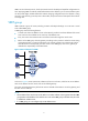
Figure 17 Network diagram for stateful failover Internet GE 1/1 GE 1/1 GE1/2 Firewall A GE 1/2 Firewall B Failover link GE1/3 GE1 /3 Internal network Host A Host B Introduction to stateful failover states Stateful failover includes the following states: • Silence: Indicates that the device has just started and is waiting for the stable running of the system, or the state between synchronization and independence.
Introduction to asymmetric path The stateful failover feature supports asymmetric path. When two firewalls operate properly, traffic can pass through one firewall to the internal network and go out through the other firewall. The session passes through one of the two firewalls randomly when leaving the internal network to achieve load sharing.
Table 7 Current stateful failover configuration information Display information Description Current Status Displays the stateful failover state of the device. Current Effective Backup Interface Displays the failover interface that is currently effective. Stateful failover configuration example Network requirements In Figure 17, Device A and Device B are deployed for stateful failover in an enterprise network to provide Internet access. They both run NAT to provide IP address translation.
7. Use a network cable or optical fiber to directly connect the failover interfaces. No intermediary device (such as a router, a switch, or a hub) is allowed between the interfaces.
Collaboration group configuration NOTE: The firewall supports configuring collaboration groups only in the web interface. Overview As shown in Figure 20, LAN users Host A, Host B and Host C access the Internet through Firewall B. When the link connecting Router A and Firewall B goes down, the traffic switches from Firewall B to the standby device Firewall C due to the fact that dynamic routing is enabled in the network.
NOTE: Collaboration applies to interfaces that are up or down simultaneously on one device. If two devices are both configured with collaboration groups and connected through interfaces in the groups, the collaboration between the two devices may fail. Configuring a collaboration group Configuration task list Table 8 Collaboration group configuration task list Task Remarks Required In this procedure, ports are assigned to a collaboration group.
Figure 21 Manage collaboration groups Figure 22 Configure a collaboration group To assign a port to the collaboration group, select the check box in front of the port and click Apply. Ports that are not selected do not belong to the collaboration group. NOTE: • A port can belong to only one collaboration group. • The page for configuring a collaboration group displays all the current member ports of the collaboration group, as well as the ports that do no belong to any collaboration group.
Displaying the status of a collaboration group and its member ports To check the status of a collaboration group, select High Reliability > Collaboration Group from the navigation tree to enter the page for displaying collaboration groups, as shown in Figure 21. To display the status of a collaboration group’s member ports, click the icon corresponding to the collaboration group to enter the page for configuring the collaboration group, as shown in Figure 22.
Track configuration NOTE: The firewall supports track configuration in the command line interface (CLI). Track overview The track module works between application and detection modules, as Figure 23 shows. It shields the differences between various detection modules from application modules. Collaboration is enabled after you associate the track module with a detection module and an application module respectively.
• NQA (see the chapter “NQA configuration”) • Interface management module Collaboration between the track module and an application module After being associated with an application module, when the status of the track entry changes, the track module notifies the application module, which then takes proper actions.
• If the consecutive failures reach the specified threshold, the NQA module tells the track module that the tracked object malfunctions. Then the track module sets the track entry to the Negative state. • If the specified threshold is not reached, the NQA module tells the track module that the tracked object functions normally. The track module then sets the track entry to the Positive state. For more information about NQA, see the chapter “NQA configuration.
Associating the track module with an application module Associating track with VRRP VRRP is an error-tolerant protocol. It adds a group of routers that can act as network gateways to a VRRP group, which forms a virtual router. Routers in the VRRP group elect the master acting as the gateway according to their priorities. A router with a higher priority is more likely to become the master. The other routers function as the backups.
To do… Use the command… Remarks Required Associate a track entry with a virtual forwarder vrrp vrid virtual-router-id weight track track-entry-number [ reduced weight-reduced ] No track entry is specified for a virtual forwarder by default. This command is supported when VRRP works in both the standard protocol mode and load balancing mode. However, this function takes effect only when VRRP works in the load balancing mode. NOTE: • Do not perform track entry monitoring on the IP address owner.
Follow these steps to associate track with static routing: To do… Use the command… Remarks Enter system view system-view — Associate the static route with a track entry to check the reachability of the next hop ip route-static dest-address { mask | mask-length } { next-hop-address | vpn-instance d-vpn-instance-name next-hop-address } track track-entry-number [ preference preference-value ] [ tag tag-value ] [ description description-text ] ip route-static vpn-instance s-vpn-instance-name&<1-6> dest-a
Configuration prerequisites Before you associate track with PBR, create a policy or a policy node and configure the match criteria as well.
• The always Invalid state of the track entry shows that the association does not take effect and each interface keeps its original forwarding state. When the track entry turns to Invalid from other state, a standby interface becomes the active interface.
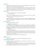
Figure 24 Network diagram for VRRP-Track-NQA collaboration configuration Virtual IP address: 10.1.1.10/24 GE0 /1 10.1.1 .1/24 GE 0/2 10.1.2.1/24 Eth 1/1 10 .1 .2.2/24 Firewall A Router A 10.1.1.3/24 20.1.1.1/24 Internet Host B Host A GE 0/1 10.1.1.2 /24 GE 0/2 10.1.3.1/24 Firewall B Eth 1/1 10 .1 .3.2/24 Router B Configuration procedure 1. Configure the IP address of each interface as shown in Figure 24. 2. Configure an NQA test group on Firewall A.
# Set the authentication mode of VRRP group 1 to simple, and the authentication key to hello. [FirewallA-GigabitEthernet0/1] vrrp vrid 1 authentication-mode simple hello # Configure the master to send VRRP packets at an interval of five seconds. [FirewallA-GigabitEthernet0/1] vrrp vrid 1 timer advertise 5 # Configure Firewall A to work in preemptive mode, and set the preemption delay to five seconds.
Total number of virtual routers : 1 Interface GigabitEthernet0/1 VRID : 1 Adver Timer : 5 Admin Status : Up State : Backup Config Pri : 100 Running Pri : 100 Preempt Mode : Yes Delay Time : 5 Auth Type : Simple Key : hello Virtual IP : 10.1.1.10 Master IP : 10.1.1.1 The output information indicates that in VRRP group 1, Firewall A is the master and Firewall B is a backup. Packets from Host A to Host B are forwarded through Firewall A.
The output information indicates that when there is a fault on the link between Firewall A and Router C, the priority of Firewall A decreases to 80. Firewall A becomes the backup, and Firewall B becomes the master. Packets from Host A to Host B are forwarded through Firewall B. Static routing-track-NQA collaboration configuration example Network requirements • As shown in Figure 25, the next hop of the static route from Firewall to Router C is Router B.
[Firewall] nqa schedule admin test start-time now lifetime forever 4. Configure a track entry on Firewall. # Configure track entry 1, and associate it with reaction entry 1 of the NQA test group (with the administrator admin, and the operation tag test). [Firewall] track 1 nqa entry admin test reaction 1 5. Verify the configuration # Display information of the track entry on Firewall.
Destination/Mask Proto 10.2.1.0/24 10.2.1.2/32 Pre Cost NextHop Interface Direct 0 0 10.2.1.2 GE0/1 Direct 0 0 127.0.0.1 InLoop0 127.0.0.0/8 Direct 0 0 127.0.0.1 InLoop0 127.0.0.1/32 Direct 0 0 127.0.0.1 InLoop0 The output information indicates the NQA test result, that is, the next hop 10.2.1.1 is unreachable (the status of the track entry is Negative), and the configured static route is invalid.
[FirewallA-GigabitEthernet0/1] vrrp vrid 1 priority 110 # Configure to monitor track entry 1 and specify the priority decrement as 30. [FirewallA-GigabitEthernet0/1] vrrp vrid 1 track 1 reduced 30 4. Configure VRRP on Firewall B. system-view [FirewallB] interface gigabitethernet 0/1 # Create VRRP group 1, and configure the virtual IP address 10.1.1.10 for the group. [FirewallB-GigabitEthernet0/1] vrrp vrid 1 virtual-ip 10.1.1.10 5.
[FirewallA-GigabitEthernet0/2] shutdown After shutting down the uplink interface on Firewall A, you can still successfully ping Host B on Host A. Use the display vrrp command to view information about VRRP group 1. # After shutting down the uplink interface on Firewall A, display detailed information about VRRP group 1 on Firewall A.
NQA configuration NOTE: The firewall supports NQA configuration only in the command line interface (CLI). NQA overview Network Quality Analyzer (NQA) can perform various types of tests and collect network performance and service quality parameters such as delay jitter, time for establishing a TCP connection, time for establishing an FTP connection, and file transfer rate.
• A detection module monitors specific objects, such as the link status, and network performance, and informs the track module of detection results. • Upon the detection results, the track module changes the status of the track entry and informs the associated application module. The track module works between the application modules and the detection modules. It hides the differences among detection modules from application modules.
NQA client and server A device with NQA test groups configured is an NQA client and the NQA client initiates NQA tests. An NQA server makes responses to probe packets destined to the specified destination address and port number. Figure 28 Relationship between the NQA client and NQA server Not all test types require the NQA server. Only the TCP, UDP echo, UDP jitter, or voice test requires both the NQA client and server, as shown in Figure 28.
Task Remarks Configuring DNS tests Configuring HTTP tests Configuring UDP jitter tests Configuring SNMP tests Configuring TCP tests Configuring UDP echo tests Configuring voice tests Configuring DLSw tests Configuring the collaboration function Optional Configuring trap delivery Optional Configuring the NQA statistics collection function Optional Configuring the history records saving function Optional Configuring optional parameters for an NQA test group Optional Configuring a schedule for an N
To do… Use the command… Enable the NQA client nqa agent enable Remarks Optional Enabled by default. Creating an NQA test group Create an NQA test group before you configure NQA tests.
To do… Apply ICMP echo tests to the specified VPN Configure the source interface for ICMP echo requests. The requests take the IP address of the source interface as their source IP address when no source IP address is specified. Use the command… Remarks Optional vpn-instance instance By default, ICMP echo tests apply to the public network. Optional source interface interface-type interface-number By default, no source interface is configured for probe packets.
To do… Use the command… Remarks Required Specify an interface to perform DHCP tests operation interface interface-type interface-number Configure optional parameters See “Configuring optional parameters for an NQA test group” By default, no interface is configured to perform DHCP tests. The specified interface must be up; otherwise, no probe packets can be sent out. Optional NOTE: • The interface that performs DHCP tests does not change its IP address.
Configuring FTP tests FTP tests of an NQA test group are used to test the connection between the NQA client and an FTP server and the time required for the FTP client to transfer a file to or download a file from the FTP server. Configuration prerequisites Before you start FTP tests, configure the FTP server. For example, configure a username and password that are used to log in to the FTP server.
NOTE: • When you execute the put command, a file file-name with fixed size and content is created on the FTP server; when you execute the get command, the device does not save the files obtained from the FTP server. • When you download a file that does not exist on the FTP server, FTP tests fail. • When you execute the get command, use a file with a small size. A big file may result in test failure due to timeout, or may affect other services for occupying too much network bandwidth.
To do… Use the command… Remarks Configure optional parameters See “Configuring optional parameters for an NQA test group” Optional NOTE: The TCP port must be port 80 on the HTTP server for NQA HTTP tests. Configuring UDP jitter tests NOTE: Do not perform NQA UDP jitter tests on known ports, ports from 1 to 1023. Otherwise, UDP jitter tests might fail or the corresponding services of this port might be unavailable. Real-time services such as voice and video have high requirements on delay jitters.
To do… Use the command… Remarks Required Configure the destination port of UDP packets destination port port-number Specify the source port number of UDP packets source port port-number Configure the size of the data field in each UDP packet data-size size By default, no destination port number is configured. The destination port must be the same as that of the listening service on the NQA server. Optional By default, no source port number is specified. Optional 100 bytes by default.
Configuration prerequisites Before you start SNMP tests, enable the SNMP agent function on the device that serves as an SNMP agent. For more information about the SNMP agent configuration, see Network Management Configuration Guide.
To do… Use the command… Remarks Enter NQA test group view nqa entry admin-name operation-tag — Configure the test type as TCP and enter test type view type tcp Required Required Configure the destination address of TCP probe packets By default, no destination IP address is configured. destination ip ip-address The destination address must be the same as the IP address of the listening service configured on the NQA server.
To do… Use the command… Remarks Required Configure the destination address of UDP packets destination ip ip-address By default, no destination IP address is configured. The destination address must be the IP address of the listening service configured on the NQA server.
3. Upon receiving the packet, the source calculates results, such as the delay jitter and one-way delay based on the packet time stamps. The statistics reflect network performance. Voice test result also includes the following parameters that reflect VoIP network performance: • Calculated Planning Impairment Factor (ICPIF)—Measures impairment to voice quality in a VoIP network. It is decided by packet loss and delay. A higher value represents a lower service quality.
To do… Use the command… Remarks Optional By default, no source IP address is specified. Specify the source IP address of probe packets source ip ip-address Specify the source port number of probe packets source port port-number The source IP address must be the IP address of a local interface. The local interface must be up; otherwise, no probe packets can be sent out. Optional By default, no source port number is specified. Optional By default, the probe packet size depends on the codec type.
To do… Use the command… Remarks Enter system view System-view — Enter NQA test group view nqa entry admin-name operation-tag — Configure the test type as DLSw and enter test type view type dlsw Required Configure the destination address of probe packets Required destination ip ip-address By default, no destination IP address is configured.
Configuring trap delivery Traps can be sent to the network management server when a test completes, fails or a probe fails. Configuration prerequisites Before you configure trap delivery, configure the destination address of the trap message with the snmp-agent target-host command, create an NQA test group, and configure related parameters.
To do… Use the command… Configure the interval for collecting the statistics of test results statistics interval interval Remarks Optional 60 minutes by default. Optional 2 by default. Configure the maximum number of statistics groups that can be kept statistics max-group number Configure the hold time of statistics groups statistics hold-time hold-time To disable collecting NQA statistics, set the maximum number to 0. Optional 120 minutes by default.
Configuring optional parameters for an NQA test group Optional parameters for an NQA test group are valid only for tests in this test group. Unless otherwise specified, the following optional parameters are applicable to all test types.
Configuring a schedule for an NQA test group You can configure a schedule for an NQA test group by setting the start time and test duration for a test group. A test group performs tests between the scheduled start time and the end time (the start time plus test duration). If the scheduled start time is ahead of the system time, the test group starts testing immediately. If both the scheduled start and end time are behind the system time, no test will start.
NQA configuration examples ICMP echo test configuration example Network requirements Use the NQA ICMP function to test whether the NQA client (Firewall) can send packets to the specified destination (Device) and test the roundtrip time of packets. Figure 29 Network diagram for ICMP echo tests Configuration procedure # Create an ICMP echo test group and configure related test parameters.
Failures due to sequence error: 0 Failures due to internal error: 0 Failures due to other errors: 0 Packet(s) arrived late: 0 # Display the history of ICMP echo tests. [Firewall] display nqa history admin test NQA entry(admin admin, tag test) history record(s): Index Response Status Time 370 3 Succeeded 2007-08-23 15:00:01.2 369 3 Succeeded 2007-08-23 15:00:01.2 368 3 Succeeded 2007-08-23 15:00:01.2 367 5 Succeeded 2007-08-23 15:00:01.2 366 3 Succeeded 2007-08-23 15:00:01.
NQA entry(admin admin, tag test) test results: Send operation times: 1 Receive response times: 1 Min/Max/Average round trip time: 512/512/512 Square-Sum of round trip time: 262144 Last succeeded probe time: 2007-11-22 09:54:03.
# Display results of the last DNS test. [Firewall] display nqa result admin test NQA entry(admin admin, tag test) test results: Destination IP address: 10.2.2.2 Send operation times: 1 Receive response times: 1 Min/Max/Average round trip time: 62/62/62 Square-Sum of round trip time: 3844 Last succeeded probe time: 2008-11-10 10:49:37.
# Enable the saving of history records. [Firewall-nqa-admin-test-ftp] history-record enable [Firewall-nqa-admin-test-ftp] quit # Enable FTP test. [Firewall] nqa schedule admin test start-time now lifetime forever # Disable FTP test after the test begins for a period of time. [Firewall] undo nqa schedule admin test # Display results of the last FTP test. [Firewall] display nqa result admin test NQA entry(admin admin, tag test) test results: Destination IP address: 10.2.2.
[Firewall-nqa-admin-test] type http [Firewall-nqa-admin-test-http] destination ip 10.2.2.2 [Firewall-nqa-admin-test-http] operation get [Firewall-nqa-admin-test-http] url /index.htm [Firewall-nqa-admin-test-http] http-version v1.0 # Enable the saving of history records. [Firewall-nqa-admin-test-http] history-record enable [Firewall-nqa-admin-test-http] quit # Enable HTTP test.
Configuration procedure 1. Configure Device # Enable the NQA server and configure the listening IP address as 10.2.2.2 and port number as 9000. system-view [Device] nqa server enable [Device] nqa server udp-echo 10.2.2.2 9000 2. Configure Firewall # Create a UDP jitter test group and configure related test parameters. system-view [Firewall] nqa entry admin test [Firewall-nqa-admin-test] type udp-jitter [Firewall-nqa-admin-test-udp-jitter] destination ip 10.2.2.
Negative SD number: 4 Negative DS number: 5 Negative SD sum: 38 Negative DS sum: 52 Negative SD average: 10 Negative DS average: 10 Negative SD square sum: 460 Negative DS square sum: 754 One way results: Max SD delay: 15 Max DS delay: 16 Min SD delay: 7 Min DS delay: 7 Number of SD delay: 10 Number of DS delay: 10 Sum of SD delay: 78 Sum of DS delay: 85 Square sum of SD delay: 666 Square sum of DS delay: 787 SD lost packet(s): 0 DS lost packet(s): 0 Lost packet(s) for unknown reason: 0
Number of SD delay: 410 Number of DS delay: 410 Sum of SD delay: 3705 Sum of DS delay: 3891 Square sum of SD delay: 45987 Square sum of DS delay: 49393 SD lost packet(s): 0 DS lost packet(s): 0 Lost packet(s) for unknown reason: 0 NOTE: The display nqa history command cannot show you the results of UDP jitter tests.
[Firewall] display nqa result admin test NQA entry(admin admin, tag test) test results: Destination IP address: 10.2.2.2 Send operation times: 1 Receive response times: 1 Min/Max/Average round trip time: 50/50/50 Square-Sum of round trip time: 2500 Last succeeded probe time: 2007-11-22 10:24:41.
[Firewall-nqa-admin-test-tcp] destination port 9000 # Enable the saving of history records. [Firewall-nqa-admin-test-tcp] history-record enable [Firewall-nqa-admin-test-tcp] quit # Enable TCP test. [Firewall] nqa schedule admin test start-time now lifetime forever # Disable TCP test after the test begins for a period of time. [Firewall] undo nqa schedule admin test # Display results of the last TCP test.
system-view [Device] nqa server enable [Device] nqa server udp-echo 10.2.2.2 8000 2. Configure Firewall # Create a UDP echo test group and configure related test parameters. system-view [Firewall] nqa entry admin test [Firewall-nqa-admin-test] type udp-echo [Firewall-nqa-admin-test-udp-echo] destination ip 10.2.2.2 [Firewall-nqa-admin-test-udp-echo] destination port 8000 # Enable the saving of history records.
Figure 38 Network diagram for voice tests Configuration procedure 1. Configure Device # Enable the NQA server and configure the listening IP address as 10.2.2.2 and port number as 9000. system-view [Device] nqa server enable [Device] nqa server udp-echo 10.2.2.2 9000 2. Configure Firewall # Create a voice test group and configure related test parameters.
Positive SD number: 257 Positive DS number: 259 Positive SD sum: 759 Positive DS sum: 1797 Positive SD average: 2 Positive DS average: 6 Positive SD square sum: 54127 Positive DS square sum: 1691967 Min negative SD: 1 Min negative DS: 1 Max negative SD: 203 Max negative DS: 1297 Negative SD number: 255 Negative DS number: 259 Negative SD sum: 759 Negative DS sum: 1796 Negative SD average: 2 Negative DS average: 6 Negative SD square sum: 53655 Negative DS square sum: 1691776 One way resul
Max negative SD: 360 Max negative DS: 1297 Negative SD number: 1028 Negative DS number: 1022 Negative SD sum: 1028 Negative DS sum: 1022 Negative SD average: 4 Negative DS average: 5 Negative SD square sum: 495901 Negative DS square sum: 5419 One way results: Max SD delay: 359 Max DS delay: 985 Min SD delay: 0 Min DS delay: 0 Number of SD delay: 4 Number of DS delay: 4 Sum of SD delay: 1390 Sum of DS delay: 1079 Square sum of SD delay: 483202 Square sum of DS delay: 973651 SD lost packet
# Display the result of the last DLSw test. [Firewall] display nqa result admin test NQA entry(admin admin, tag test) test results: Destination IP address: 10.2.2.2 Send operation times: 1 Receive response times: 1 Min/Max/Average round trip time: 19/19/19 Square-Sum of round trip time: 361 Last succeeded probe time: 2007-11-22 10:40:27.
[Firewall] ip route-static 10.1.1.2 24 10.2.1.1 track 1 3. On Firewall, create an NQA test group. # Create an NQA test group with the administrator name being admin and operation tag being test. [Firewall] nqa entry admin test # Configure the test type of the NQA test group as ICMP echo. [Firewall-nqa-admin-test] type icmp-echo # Configure the destination IP address of the ICMP echo test operation as 10.2.1.1. [Firewall-nqa-admin-test-icmp-echo] destination ip 10.2.1.
system-view [RouterA] interface ethernet 1/1 [RouterA-Ethernet1/1] undo ip address # On Firewall, display information about all the track entries. [Firewall] display track all Track ID: 1 Status: Negative Notification delay: Positive 0, Negative 0 (in seconds) Reference object: NQA entry: admin test Reaction: 1 # Display brief information about active routes in the routing table on Firewall. [Firewall] display ip routing-table Routing Tables: Public Destinations : 4 Destination/Mask Proto 10.
Ethernet Link Aggregation Configuration This chapter includes these sections: • Overview • Ethernet Link Aggregation Configuration Task List • Configuring an Aggregation Group • Configuring an Aggregate Interface • Configuring Load Sharing for Link Aggregation Groups • Displaying and Maintaining Ethernet Link Aggregation • Ethernet Link Aggregation Configuration Examples NOTE: Only the Firewall A-F5000 supports link aggregation, and only supports static mode.
same is created automatically. For example, when you create interface Bridge-aggregation 1, Layer 2 aggregation group 1 is created. To a Layer 2 aggregation group, you can assign only Layer 2 Ethernet interfaces; to a Layer 3 aggregation group, only Layer 3 Ethernet interfaces. NOTE: • On a Layer 3 aggregate interface, you can create subinterfaces. These subinterfaces are logical interfaces that operate at the network layer. They can receive VLAN tagged packets for their Layer 3 aggregate interface.
NOTE: • Class-two configurations made on an aggregate interface are automatically synchronized to all its member ports. These configurations are retained on the member ports even after the aggregate interface is removed. • Any class-two configuration change may affect the aggregation state of link aggregation member ports and thus ongoing traffic.
Table 12 LACP priorities Type System LACP priority Port aggregation priority Description Remarks Used by two peer devices (or systems) to determine which one is superior in link aggregation. In dynamic link aggregation, the system that has higher system LACP priority sets the selected state of member ports on its side first and then the system that has lower priority sets port state accordingly. Determines the likelihood of a member port to be selected on a system.
Selecting a reference port The system selects a reference port from the member ports that are in the up state and have the same class-two configurations as the aggregate interface. The candidate ports are sorted by aggregation priority, duplex and speed in this order: lowest aggregation priority, full duplex/high speed, full duplex/low speed, half duplex/high speed, and half duplex/low speed. The one at the top is selected as the reference port.
NOTE: • Because any port attribute or class-two configuration change on a member port may cause the aggregation state of the port and other member ports to change and thus affect services, it is recommended that you do that with caution. • A port that joins the static aggregation group after the selected port limit has been reached will not be placed in the selected state even if it should be in normal cases. This is to prevent the ongoing traffic on the current selected ports from being interrupted.
Figure 43 Set the state of a member port in a dynamic aggregation group Meanwhile, the system with the higher system ID, being aware of the aggregation state changes on the remote system, changes the aggregation state of its ports accordingly. NOTE: • Because any port attribute or class-two configuration change on a member port may cause the aggregation state of the port and other member ports to change and thus affect services, it is recommended that you do that with caution.
• IP addresses carried in packets • Port numbers carried in packets • IP protocols used by packets Alternatively, you can let the system automatically choose link-aggregation load sharing criterion or criteria based on packet types (Layer 2, IPv4, or IPv6 for example).
Table 15 Interfaces that cannot be assigned to a Layer 3 aggregation group Interface type Reference Interfaces configured as DHCP/BOOTP clients DHCP in the Firewall WEB Volume VRRP-enabled interfaces VRRP in the Firewall WEB Volume Portal-enabled interfaces Portal Configuration in the Security Volume NOTE: Removing an aggregate interface also removes the corresponding aggregation group. At the same time, all the member ports of the aggregation group, if any, leave the aggregation group.
To do... Use the command... Remarks Exit to system view quit — Enter Layer 3 Ethernet interface view interface interface-type interface-number Required Assign the Ethernet interface to the aggregation group port link-aggregation group number Repeat these two steps to assign multiple Layer 3 Ethernet interfaces to the aggregation group.
To do... Use the command... Remarks Optional Assign the port an aggregation priority Set the LACP timeout interval on the port to the short timeout interval (1 second) link-aggregation port-priority port-priority By default, the aggregation priority of a port is 32768. Changing the aggregation priority of a port may affect the aggregation state of the ports in the dynamic aggregation group.
To do... Use the command... Remarks Optional By default, the LACP priority of a port is 32768. Assign the port a LACP priority lacp port-priority port-priority Changing the LACP priority of a port may affect the aggregation state of ports in the dynamic aggregation group.
Configuring the MTU of a Layer 3 Aggregate Interface/Subinterface Maximum transmission unit (MTU) of an interface affects IP packets fragmentation and reassembly on the interface. Follow these steps to change the MTU of a Layer 3 aggregate interface/subinterface: To do... Use the command... Remarks Enter system view system-view — Enter Layer 3 aggregate interface/subinterface view interface route-aggregation { interface-number | interface-number.
Link aggregation increase bandwidth by aggregating multiple physical Ethernet links into one logical link, called an aggregate link. The bandwidth of an aggregate link depends on the number of selected ports in the corresponding aggregation group. To prevent congestion on an aggregate link when the corresponding aggregation group contains too few selected ports, you can configure the minimum number of selected ports in the corresponding aggregation group required for bringing up the aggregate interface.
NOTE: • When configuring this feature in a static link aggregation group, make sure that you configure the same settings on the aggregation group at the other end of the aggregate link. • Configuring the minimum number of selected ports required to bring up an aggregation group may cause all the member ports in the current aggregation group to become unselected.
them. Alternatively, you can let the system automatically choose link-aggregation load sharing criterion or criteria based on packet types (Layer 2, IPv4, or IPv6 for example). You can configure global or group-specific load sharing criteria. A link aggregation group preferentially uses the group-specific load sharing criteria. If no group-specific load sharing criteria is available, it uses the global load sharing criteria.
To do... Use the command...
[FirewallA] vlan 10 [FirewallA-vlan10] port gigabitethernet 0/4 [FirewallA-vlan10] quit # Create VLAN 20, and assign port GigabitEthernet 0/5 to VLAN 20. [FirewallA] vlan 20 [FirewallA-vlan20] port gigabitethernet 0/5 [FirewallA-vlan20] quit # Create Layer 2 aggregate interface Bridge-Aggregation 1. [FirewallA] interface bridge-aggregation 1 [FirewallA-Bridge-Aggregation1] quit # Assign ports GigabitEthernet 0/1 through GigabitEthernet 0/3 to link aggregation group 1.
The output shows that link aggregation group 1 is a load shared Layer 2 static aggregation group and it contains three selected ports. Layer 2 Dynamic Aggregation Configuration Example Network requirements As shown in Figure 45: • Firewall A and Firewall B are connected through their respective Layer 2 Ethernet interfaces GigabitEthernet 0/1 through GigabitEthernet 0/3.
[FirewallA-GigabitEthernet0/1] quit [FirewallA] interface gigabitethernet 0/2 [FirewallA-GigabitEthernet0/2] port link-aggregation group 1 [FirewallA-GigabitEthernet0/2] quit [FirewallA] interface gigabitethernet 0/3 [FirewallA-GigabitEthernet0/3] port link-aggregation group 1 [FirewallA-GigabitEthernet0/3] quit # Configure Layer 2 aggregate interface Bridge-Aggregation 1 as a trunk port and assign it to VLANs 10 and 20.
• Configure the load sharing criterion for link aggregation group 1 as the source IP addresses of packets and the load sharing criterion for link aggregation group 2 as the destination IP addresses of packets to enable traffic to be load-shared across aggregation group member ports. Figure 46 Network diagram for Layer 2 aggregation load sharing configuration Configuration procedure Step1 Configure Firewall A # Create VLAN 10, and assign port GigabitEthernet 0/5 to VLAN 10.
[FirewallA-Bridge-Aggregation1] port trunk permit vlan 10 20 Please wait... Done. Configuring GigabitEthernet0/1... Done. Configuring GigabitEthernet0/2... Done. [FirewallA-Bridge-Aggregation1] quit # Create Layer 2 aggregate interface Bridge-Aggregation 2, and configure the load sharing criterion for the link aggregation group as the destination IP addresses of packets.
# Display all the group-specific load sharing criteria on Firewall A. [FirewallA] display link-aggregation load-sharing mode interface Bridge-Aggregation1 Load-Sharing Mode: source-ip address Bridge-Aggregation2 Load-Sharing Mode: destination-ip address The output above shows that the load sharing criterion for link aggregation group 1 is the source IP addresses of packets and that for link aggregation group 2 is the destination IP addresses of packets.
[FirewallA-GigabitEthernet0/3] quit # Configure the global link-aggregation load sharing criteria as the source and destination IP addresses of packets. [FirewallA] link-aggregation load-sharing mode source-ip destination-ip Step2 Configure Firewall B Configure Firewall B as you configure Firewall A. Step3 Verify the configurations # Display the summary information about all aggregation groups on Firewall A.
Figure 48 Network diagram for Layer 3 dynamic aggregation Configuration procedure Step1 Configure Firewall A # Create Layer 3 aggregate interface Route-aggregation 1, configure the link aggregation mode as dynamic, and configure an IP address and subnet mask for the aggregate interface. system-view [FirewallA] interface route-aggregation 1 [FirewallA-Route-Aggregation1] link-aggregation mode dynamic [FirewallA-Route-Aggregation1] ip address 192.168.1.
The output shows that link aggregation group 1 is a load-shared Layer 3 dynamic aggregation group and it contains three selected ports. # Display the global link-aggregation load sharing criteria on Firewall A. [FirewallA] display link-aggregation load-sharing mode Link-Aggregation Load-Sharing Mode: destination-ip address, source-ip address The output shows that the global link-aggregation load sharing criteria are the source and destination IP addresses of packets.
# Create Layer 3 aggregate interface Route-Aggregation 2, configure its link aggregation group to perform load sharing based on destination IP address, and configure an IP address and subnet mask for the aggregate interface. [FirewallA] interface route-aggregation 2 [FirewallA-Route-Aggregation2] link-aggregation load-sharing mode destination-ip [FirewallA-Route-Aggregation2] ip address 192.168.2.
Support and other resources Contacting HP For worldwide technical support information, see the HP support website: http://www.hp.
Conventions This section describes the conventions used in this documentation set. Command conventions Convention Description Boldface Bold text represents commands and keywords that you enter literally as shown. Italic Italic text represents arguments that you replace with actual values. [] Square brackets enclose syntax choices (keywords or arguments) that are optional. { x | y | ... } Braces enclose a set of required syntax choices separated by vertical bars, from which you select one.
Network topology icons Represents a generic network device, such as a router, switch, or firewall. Represents a routing-capable device, such as a router or Layer 3 switch. Represents a generic switch, such as a Layer 2 or Layer 3 switch, or a router that supports Layer 2 forwarding and other Layer 2 features. Represents a firewall chassis or a firewall module. Port numbering in examples The port numbers in this document are for illustration only and might be unavailable on your device.
Index ACDENORSTV Displaying and Maintaining Ethernet Link Aggregation,113 A Associating the track module with a detection module,44 Displaying and maintaining NQA,79 Displaying and maintaining track entries,50 Associating the track module with an application module,46 E Enabling the NQA client,62 C Ethernet Link Aggregation Configuration Examples,114 Collaboration group configuration example,42 Ethernet Link Aggregation Configuration Task List,105 Configuration guidelines,37 Configuration VRRP in t