
R3166-R3206-HP High-End Firewalls High Availability Configuration Guide-6PW101

116
The output shows that link aggregation group 1 is a load shared Layer 2 static aggregation group and
it contains three selected ports.
Layer 2 Dynamic Aggregation Configuration Example
Network requirements
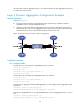
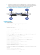
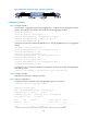
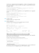
As shown in Figure 45:
• Firewall A and Firewall B are connected through their respective Layer 2 Ethernet interfaces
GigabitEthernet 0/1 through GigabitEthernet 0/3.
• Configure a Layer 2 dynamic link aggregation group on Firewall A and Firewall B respectively,
enable VLAN 10 at one end of the aggregate link to communicate with VLAN 10 at the other end,
and VLAN 20 at one end to communicate with VLAN 20 at the other end.
Figure 45 Network diagram for Layer 2 dynamic aggregation
Configuration procedure
Step1 Configure Firewall A
# Create VLAN 10, and assign port GigabitEthernet 0/4 to VLAN 10.
<FirewallA> system-view
[FirewallA] vlan 10
[FirewallA-vlan10] port gigabitethernet 0/4
[FirewallA-vlan10] quit
# Create VLAN 20, and assign port GigabitEthernet 0/5 to VLAN 20.
[FirewallA] vlan 20
[FirewallA-vlan20] port gigabitethernet 0/5
[FirewallA-vlan20] quit
# Create Layer 2 aggregate interface Bridge-aggregation 1, and configure the link aggregation mode
as dynamic.
[FirewallA] interface bridge-aggregation 1
[FirewallA-Bridge-Aggregation1] link-aggregation mode dynamic
# Assign ports GigabitEthernet 0/1 through GigabitEthernet 0/3 to link aggregation group 1 one at a
time.
[FirewallA] interface gigabitethernet 0/1
[FirewallA-GigabitEthernet0/1] port link-aggregation group 1