
R3166-R3206-HP High-End Firewalls High Availability Configuration Guide-6PW101

118
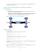
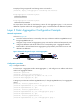
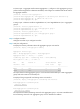
• Configure the load sharing criterion for link aggregation group 1 as the source IP addresses of
packets and the load sharing criterion for link aggregation group 2 as the destination IP addresses
of packets to enable traffic to be load-shared across aggregation group member ports.
Figure 46 Network diagram for Layer 2 aggregation load sharing configuration
Configuration procedure
Step1 Configure Firewall A
# Create VLAN 10, and assign port GigabitEthernet 0/5 to VLAN 10.
<FirewallA> system-view
[FirewallA] vlan 10
[FirewallA-vlan10] port gigabitethernet 0/5
[FirewallA-vlan10] quit
# Create VLAN 20, and assign port GigabitEthernet 0/6 to VLAN 20.
<FirewallA> system-view
[FirewallA] vlan 20
[FirewallA-vlan20] port gigabitethernet 0/6
[FirewallA-vlan20] quit
# Create Layer 2 aggregate interface Bridge-Aggregation 1, and configure the load sharing criterion for
the link aggregation group as the source IP addresses of packets.
[FirewallA] interface bridge-aggregation 1
[FirewallA-Bridge-Aggregation1] link-aggregation load-sharing mode source-ip
[FirewallA-Bridge-Aggregation1] quit
# Assign ports GigabitEthernet 0/1 and GigabitEthernet 0/2 to link aggregation group 1.
[FirewallA] interface gigabitethernet 0/1
[FirewallA-GigabitEthernet0/1] port link-aggregation group 1
[FirewallA-GigabitEthernet0/1] quit
[FirewallA] interface gigabitethernet 0/2
[FirewallA-GigabitEthernet0/2] port link-aggregation group 1
[FirewallA-GigabitEthernet0/2] quit
# Configure Layer 2 aggregate interface Bridge-Aggregation 1 as a trunk port and assign it to VLANs
10 and 20.
[FirewallA] interface bridge-aggregation 1
[FirewallA-Bridge-Aggregation1] port link-type trunk