
R3166-R3206-HP High-End Firewalls High Availability Configuration Guide-6PW101

121
[FirewallA-GigabitEthernet0/3] quit
# Configure the global link-aggregation load sharing criteria as the source and destination IP addresses
of packets.
[FirewallA] link-aggregation load-sharing mode source-ip destination-ip
Step2 Configure Firewall B
Configure Firewall B as you configure Firewall A.
Step3 Verify the configurations
# Display the summary information about all aggregation groups on Firewall A.
[FirewallA] display link-aggregation summary
Aggregation Interface Type:
BAGG -- Bridge-Aggregation, RAGG -- Route-Aggregation
Aggregation Mode: S -- Static, D -- Dynamic
Loadsharing Type: Shar -- Loadsharing, NonS -- Non-Loadsharing
Actor System ID: 0x8000, 000f-e2ff-0001
AGG AGG Partner ID Select Unselect Share
Interface Mode Ports Ports Type
-------------------------------------------------------------------------------
RAGG1 S none 3 0 Shar
The output above shows that link aggregation group 1 is a load-sharing-capable Layer 3 static
aggregation group that contains three selected ports.
# Display the global link-aggregation load sharing criteria on Firewall A.
[FirewallA] display link-aggregation load-sharing mode
Link-Aggregation Load-Sharing Mode:
destination-ip address, source-ip address
The output above shows that the global link-aggregation load sharing criteria are the source and
destination IP addresses of packets.
Layer 3 Dynamic Aggregation Configuration Example
Network requirements
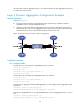
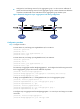
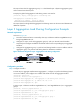
As shown in Figure 48:
• Firewall A and Firewall B are connected by their Layer 3 Ethernet interfaces GigabitEthernet 0/1
through GigabitEthernet 0/3.
• Configure a Layer 3 dynamic link aggregation group on Firewall A and Firewall B respectively and
configure IP addresses and subnet masks for the corresponding Layer 3 aggregate interfaces.
• Enable traffic to be load-shared across aggregation group member ports based on source and
destination IP addresses.