
R3166-R3206-HP High-End Firewalls High Availability Configuration Guide-6PW101


37
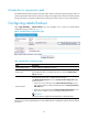
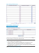
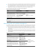
Table 7 Current stateful failover configuration information
Dis
p
la
y
information Descri
p
tion
Current Status Displays the stateful failover state of the device.
Current Effective Backup Interface Displays the failover interface that is currently effective.
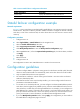
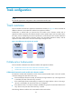
Stateful failover configuration example
Network requirements
In Figure 17, Device A and Device B are deployed for stateful failover in an enterprise network to provide
Internet access. They both run NAT to provide IP address translation. Configure the devices to backup
each other, so that when one device fails, the other device takes over the services to ensure service
continuity.
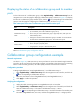
Configuration procedure
1. Configure Device A.
• Select high reliability > Stateful Failover from the navigation tree.
• Select the Enable Stateful Failover check box.
• Select Support Asymmetric Path for Backup Type.
• Click Modify Backup Interface to enter the Backup Interface Configuration page.
• Select GigabitEthernet 1/2 from the Optional Backup Interface(s) list, click the << button, and then
click Apply.
• Click Apply.
• Reboot Device A.
2. Configure Device B.
The configuration on Device B is omitted because it is similar to that on Device A.
Configuration guidelines
1. You must configure VRRP or a dynamic routing protocol on the devices and the uplink/downlink
devices to ensure that the traffic can automatically switch to the other device if one device fails.
2. Only two stateful failover devices are supported.
3. The same failover interfaces—with the same type and number—must exist on the two devices.
Otherwise, data backup fails.
4. If an Ethernet interface is the current backup interface, you cannot configure other functions or
parameters on the Ethernet interface.
5. To run NAT on two hot backup devices, you must configure two identical NAT address pools for
each device, but the higher-priority address pool on a device must be different from that on the
other; otherwise, a conflict may occur during stateful failover. For example, you can configure two
NAT address pools, 100.0.0.1 through 100.0.0.5 (Pool 1), and 100.0.0.6 through 100.0.0.10
(Pool 2) on devices A and B. Pool 1 has a lower priority on Device A, while Pool 2 has a lower
priority on Device B. For more information, see NAT and ALG Configuration Guide.
6. If you click Modify Backup Interface before clicking Apply, the configurations you have made on
the stateful failover configuration page will be lost.