HP High-End Firewalls NAT and ALG Configuration Guide Part number: 5998-2629 Software version: F1000-E/Firewall module: R3166 F5000-A5: R3206 Document version: 6PW101-20120706
Legal and notice information © Copyright 2012 Hewlett-Packard Development Company, L.P. No part of this documentation may be reproduced or transmitted in any form or by any means without prior written consent of Hewlett-Packard Development Company, L.P. The information contained herein is subject to change without notice.
Contents NAT configuration ······················································································································································· 1 Overview············································································································································································ 1 Introduction to NAT ································································································································
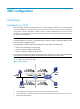
NAT configuration Overview Introduction to NAT Network Address Translation (NAT) provides a way of translating the IP address in an IP packet header to another IP address. In practice, NAT is primarily used to allow users using private IP addresses to access public networks. With NAT, a smaller number of public IP addresses are used to meet public network access requirements from a larger number of private hosts, and thus NAT effectively alleviating the depletion of IP addresses.
• Upon receipt of the packet, the NAT gateway checks the IP header. Finding that the packet is destined to the external network, the NAT gateway translates the private source IP address 192.168.1.3 to the globally unique IP address 20.1.1.1 and then forwards the resulting packet to the external server. Meanwhile, the NAT gateway records the mapping between the two addresses in its NAT table. • After receiving a response from the external server, the NAT gateway uses the destination IP address 20.1.1.
NAT control can be achieved through ACLs. Only packets matching the ACL rules are served by NAT. NAPT Network Address Port Translation (NAPT) is a variation of NAT. It allows multiple internal addresses to be mapped to the same public IP address, which is called multiple-to-one NAT or address multiplexing. NAPT mapping is based on both the IP address and the port number. With NAPT, packets from multiple internal hosts are mapped to the same external IP address with different port numbers.
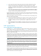
DNS mapping As introduced above, you can specify a public IP address and port number for an internal server on the public network interface of a NAT gateway, so that external users can access the internal server using its domain name or pubic IP address. Figure 3 Diagram for NAT DNS mapping operation In Figure 3, an internal host wants to access an internal server on the same private network by using its domain name, while the DNS server is located on the public network.
When a VPN host sends a packet to a public host, NAT replaces its private source IP address and port number with a public IP address and port number, and records the NAT entry with the relevant VPN information, such as the protocol type and router distinguisher (RD). When a response packet arrives, the NAT gateway translates its public destination IP address and port number to the private ones and sends it to the VPN host. Both NAT and NAPT support multiple-instance.
Table 1 Dynamic NAT configuration task list Task Remarks Creating an address pool Required for configuring NAPT and many-to-many NAT Required Configuring dynamic NAT • Configure dynamic NAT on an interface. Static NAT The mapping relationships between external and internal network addresses are manually configured. Static NAT can meet fixed access requirements of a few users. Perform the tasks in Table 2 to configure static NAT.
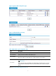
Figure 4 Dynamic NAT configuration page Figure 5 Add NAT Address Pool page Table 4 NAT address pool configuration items Item Description Index Specify the index of an address pool. Start IP Address Specify the start IP address of the address pool. End IP Address Specify the end IP address of the address pool. The end IP address must be identical to or higher than the start IP address. Configure the address pool as a low-priority or a non low-priority address pool.
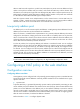
Configuring dynamic NAT Select Firewall > NAT Policy > Dynamic NAT from the navigation tree to enter the page shown in Figure 4. In the Dynamic NAT field where all dynamic NAT policies are displayed, click Add to enter the Add Dynamic NAT page shown in Figure 6. Figure 6 Add Dynamic NAT page Table 5 Dynamic NAT configuration items Item Description Interface Specify an interface on which dynamic NAT is to be enabled. Specify an ACL for dynamic NAT.
Item Description Enable track to VRRP Configure whether to associate dynamic NAT on an interface with a VRRP group, and specify the VRRP group to be associated if you associate dynamic NAT on an interface with a VRRP group. When two network devices implement both stateful failover and dynamic NAT, • Make sure that each address pool on an interface is associated with one VRRP group only; otherwise, the system associates the address pool with the VRRP group having the highest group ID.
Figure 8 Add Static Address Mapping page Table 6 Static NAT configuration item Item Description VPN Instance Specify a VPN instance name. Internal IP Address Type an internal IP address for the static address mapping. Global IP Address Type a public IP address for the static address mapping. Specify the network mask for internal and public IP addresses. Network Mask If the network mask is specified, net-to-net static NAT is implemented. If no network mask is specified, the default mask 255.255.
Item Description Enable track to VRRP Configure whether to associate static NAT on an interface with a VRRP group, and specify the VRRP group to be associated if you associate static NAT on an interface with a VRRP group. VRRP Group When two network devices implement both stateful failover and dynamic NAT, you need to add the devices to the same VRRP group, and associate dynamic NAT with the VRRP group to ensure normal switchovers between the two devices. Return to Static NAT configuration task list.
Figure 11 Add Internal Server page Table 8 Internal server configuration items Item Description Interface Specify an interface to which the internal server policy is applied. Specify a VPN instance name to which the internal server belongs. VPN Instance If the internal server belongs to a VPN, you need to specify the VPN instance. You do not need to specify it if the internal server belongs to a normal private network. Protocol Type Select or specify the type of the protocol to be carried by IP.
Item Description Specify the internal IP address(es) for the internal server. • Single box: Used to specify an internal IP address when 6(TCP) or Internal IP 17(UDP) is not selected for the protocol type or you specify a single global port. • Double boxes: Used to specify a range of internal IP addresses each of which has a one-to-one correspondence with a port in the specified range.
Table 9 DNS mapping configuration items Item Description Protocol Select the protocol supported by an internal server. Global IP Specify the external IP address of the internal server. Global Port Specify the port number of the internal server. Domain Specify the domain name of the internal server. Return to Internal server configuration task list. NAT configuration examples NAT configuration example 1.
• Select Firewall > NAT Policy > Dynamic NAT from the navigation tree, and then click Add. • Type 0 in Index. • Type 202.38.1.2 in Start IP Address. • Type 202.38.1.3 in End IP Address. • Click Apply. # Configure dynamic NAT. • Click Add in the Dynamic NAT field. • Select GigabitEthernet0/1 for Interface. • Type 2000 in ACL. • Select PAT for Address Transfer. • Type 0 in Address Pool Index. • Click Apply. Internal server configuration example 1.
• Type 10.110.10.3 in Internal IP. • Type 21 in Internal Port. • Click Apply. # Configure the Web server 1. • Click Add in the Internal Server field. • Select GigabitEthernet0/2 for Interface. • Select 6(TCP) for Protocol Type. • Click the radio button next to Assign IP Address, and then type 202.38.1.1 for Global IP. • Select the upper radio button next to Global Port and type 80. • Type 10.110.10.1 in Internal IP. • Type 80 in Internal Port. • Click Apply. # Configure Web server 2.
Configuring address translation Introduction to address translation A NAT device can be configured with or dynamically generate mappings to translate between internal and external network addresses. Address translation can be classified into static and dynamic NAT. • Static NAT Mappings between external and internal network addresses are manually configured. Static NAT can meet fixed access requirements of a few users. • Dynamic NAT A dynamic NAT entry is generated dynamically.
translate TCP/UDP port numbers. NAPT allows for many-to-one address translation by translating also TCP/UDP port numbers. Typically, a NAT entry is configured on the outbound interface of the NAT device. If internal hosts need to access external networks through multiple outbound interfaces on the NAT device, you must configure NAT entries on each of the interfaces. To avoid this, the device supports configuring a NAT entry on the inbound interface on the NAT device.
To do… Use the command… Remarks Enter interface view interface interface-type interface-number — Enable Easy IP by associating an ACL with the IP address of the interface nat outbound [ acl-number ] [ track vrrp virtual-router-id ] Required 4.
internal/external network information configurations, internal servers can be classified into common internal servers and load sharing internal servers. Both internal servers and their external IP addresses can support VPN. If an internal server belongs to an VPN, you also need to specify the vpn-instance-name argument. Without this argument specified, the internal server does not belong to any VPN. 2.
Displaying and maintaining NAT To do… Use the command… Remarks Display information about NAT address pools display nat address-group [ group-number ] Available in any view Display all NAT configuration information display nat all Available in any view Display the NAT configuration information display nat bound Available in any view Display DNS mapping configuration information display nat dns-map Available in any view Display the internal server information display nat server Available in a
Figure 16 Network diagram for dynamic NAT III 2. Configuration procedure # As shown in Figure 16, configure the IP addresses for the interfaces (omitted). # Configure address pool 1. system-view [Firewall] nat address-group 1 202.38.1.2 202.38.1.3 # Configure ACL 2001, permitting only users from network segment 10.110.10.0/24 to access the Internet. [Firewall] acl number 2001 [Firewall-acl-basic-2001] rule permit source 10.110.10.0 0.0.0.
Figure 17 Network diagram for common internal server configuration 10.110.10.1/16 10.110.10.2/16 Web server 1 Web server 2 GE0/1 10.110.10.10/16 GE0/2 202.38.1.1/24 Firewall FTP server SMTP server 10.110.10.3/16 10.110.10.4/16 2. Internet Host Configuration procedure # As shown in Figure 17, configure the IP addresses for the interfaces (omitted). # Enter interface GigabitEthernet 0/2 view. system-view [Firewall] interface gigabitethernet 0/2 # Configure the internal FTP server.
Figure 18 Network diagram for NAT DNS mapping 10.110.10.1/16 10.110.10.2/16 202.38.1.4/24 Web server FTP server DNS server GE0/1 10.110.10.10/16 GE0/2 202.38.1.1/24 Internet Firewall 2. Host A Host B 10.110.10.3/16 202.38.1.10/24 Configuration procedure # As shown in Figure 18, configure the IP addresses for the interfaces (omitted). # Enter the view of interface GigabitEthernet 0/2. system-view [Firewall] interface gigabitethernet 0/2 # Configure the internal web server.
Troubleshooting NAT Symptom 1: abnormal translation of IP addresses Solution: Enable debugging for NAT. Try to locate the problem based on the debugging display. Use other commands, if necessary, to further identify the problem. Pay special attention to the source address after the address translation and ensure that this address is the address that you intend to change to. If not, there may be an address pool bug.
Application level gateway configuration ALG overview The application level gateway (ALG) feature is used to process application layer packets. Usually, Network Address Translation (NAT) translates only IP address and port information in packet headers; it does not analyze fields in application layer payloads. However, the packet payloads of some protocols may contain IP address or port information, which, if not translated, may cause problems.
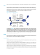
The following describes the operation of an ALG-enabled device, taking FTP as an example. As shown in Figure 19, the host in the outside network accesses the FTP server in the inside network in passive mode through the ALG-enabled device.
Configuring ALG in the web interface Enabling ALG NOTE: By default, the ALG function is enabled for all protocols. In the navigation tree, select Firewall > ALG to enter the page as shown in Figure 20. Figure 20 ALG configuration page • To add selected application protocols, select them in the Optional Application Protocols list and click the << button. Then the protocols will be added to the Selected Application Protocols list.
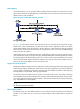
• The host in the outside network can access the FTP server in the inside network. • The company has four public network addresses: 5.5.5.1, 5.5.5.9, 5.5.5.10, and 5.5.5.11, and the FTP server uses the public network address of 5.5.5.10 to provide services to the outside. Figure 21 Network diagram for configuring FTP ALG Configuration procedure 1. Configure ALG. # Configure FTP ALG. (By default, the FTP ALG function is enabled, and thus this step can be omitted.
• Click Apply. # Configure the internal FTP server. • Select Firewall > NAT > Internal Server from the navigation tree. Then in the Internal Server area, click Add. • Select GigabitEthernet0/1. • Select 6(TCP) as the protocol type, • Type 5.5.5.10 as the external IP address. • Type 21 as the global port. • Type 192.168.1.2 as the internal IP address. • Type 21 as the internal port. • Click Apply. SIP/H.323 ALG configuration example NOTE: H.
2. Configure an ACL. # Create a basic ACL. • Select Firewall > ACL from the navigation tree and then on the page that appears, click Add. • Type 2001 in the ACL Number text box. • Click Apply. # Create an ACL rule. • Click the icon of ACL 2001 to enter the ACL rule configuration page. Then click Add. • Select Permit as the operation. • Select the Source IP Address check box, type192.168.1.0 as the source IP address, and type 0.0.0.255 as the source wildcard. • Click Apply. • Click Add.
Figure 23 Network diagram for NBT ALG configuration Configuration procedure 1. Configure ALG. # Configure NBT ALG. (By default, the NBT ALG function is enabled, and thus this step can be omitted.) • Select Firewall > ALG from the navigation tree. • Select nbt in the Optional Application Protocols list and click the << button. • Click OK. 2. Configure static NAT and the internal server. # Configure a static address mapping. • Select Firewall > NAT > Static NAT from the navigation tree.
• Type 5.5.5.10 as the external IP address. • Type 138 as the global port. • Type 192.168.1.2 as the internal IP address. • Type 138 as the internal port. • Click Apply. • In the Internal Server area, click Add. • Select GigabitEthernet1/2. • Select 6(TCP) as the protocol type, • Type 5.5.5.10 as the external IP address. • Type 139 as the global port. • Type 192.168.1.2 as the internal IP address. • Type 139 as the internal port. • Click Apply.
Figure 24 Network diagram for FTP ALG configuration 2. Configuration procedure # Configure the address pool and ACL. system-view [Firewall] nat address-group 1 5.5.5.9 5.5.5.11 [Firewall] acl number 2001 [Firewall-acl-basic-2001] rule permit [Firewall-acl-basic-2001] quit # Enable ALG for FTP. [Firewall] alg ftp # Configure NAT. [Firewall] interface ethernet 1/1 [Firewall-Ethernet1/1] nat outbound 2001 address-group 1 # Configure internal FTP server.
Figure 25 Network diagram for SIP ALG configuration 2. Configuration procedure # Configure the address pool and ACL. system-view [Firewall] nat address-group 1 5.5.5.9 5.5.5.11 [Firewall] acl number 2001 [Firewall-acl-basic-2001] rule permit source 192.168.1.0 0.0.0.255 [Firewall-acl-basic-2001] rule deny [Firewall-acl-basic-2001] quit # Enable ALG for SIP. [Firewall] alg sip # Configure NAT.
[Firewall] nat static 192.168.1.3 5.5.5.9 # Enable ALG for NBT. [Firewall] alg nbt # Configure NAT. [Firewall] interface ethernet 1/2 [Firewall-Ethernet1/2] nat outbound static # Configure the internal WINS server. [Firewall-Ethernet1/2] nat server protocol udp global 5.5.5.10 137 inside 192.168.1.2 137 [Firewall-Ethernet1/2] nat server protocol udp global 5.5.5.10 138 inside 192.168.1.2 138 [Firewall-Ethernet1/2] nat server protocol tcp global 5.5.5.10 139 inside 192.168.1.
Support and other resources Contacting HP For worldwide technical support information, see the HP support website: http://www.hp.
Conventions This section describes the conventions used in this documentation set. Command conventions Convention Description Boldface Bold text represents commands and keywords that you enter literally as shown. Italic Italic text represents arguments that you replace with actual values. [] Square brackets enclose syntax choices (keywords or arguments) that are optional. { x | y | ... } Braces enclose a set of required syntax choices separated by vertical bars, from which you select one.
Network topology icons Represents a generic network device, such as a router, switch, or firewall. Represents a routing-capable device, such as a router or Layer 3 switch. Represents a generic switch, such as a Layer 2 or Layer 3 switch, or a router that supports Layer 2 forwarding and other Layer 2 features. Represents a firewall chassis or a firewall module. Port numbering in examples The port numbers in this document are for illustration only and might be unavailable on your device.
Index ACORT A Conventions,38 ALG configuration examples,28 O ALG overview,26 Overview,1 C R Configuration guidelines,25 Related information,37 Configuring a NAT in the CLI,16 T Configuring a NAT policy in the web interface,5 Troubleshooting NAT,25 Configuring ALG in the command line interface,33 Configuring ALG in the web interface,28 Contacting HP,37 40