
R3166-R3206-HP High-End Firewalls NAT and ALG Configuration Guide-6PW101

15
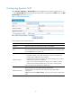
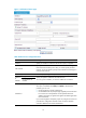
• Select Firewall > NAT Policy > Dynamic NAT from the navigation tree, and then click Add.
• Type 0 in Index.
• Type 202.38.1.2 in Start IP Address.
• Type 202.38.1.3 in End IP Address.
• Click Apply.
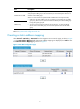
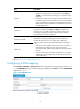
# Configure dynamic NAT.
• Click Add in the Dynamic NAT field.
• Select GigabitEthernet0/1 for Interface.
• Type 2000 in ACL.
• Select PAT for Address Transfer.
• Type 0 in Address Pool Index.
• Click Apply.
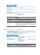
Internal server configuration example
1. Network requirements
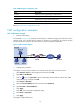
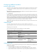
As illustrated in Figure 14, a c
ompany provides two Web servers and one FTP server for external users
to access. The internal network address is 10.110.0.0/16. The internal address for the FTP server is
10.110.10.3/16, for the Web server 1 is 10.110.10.1/16, and for the Web server 2 is 10.110.10.2/16. The
company has three public IP addresses from 202.38.1.1/24 through 202.38.1.3/24. Specifically, the
company has the following requirements:
• External hosts can access internal servers using public address 202.38.1.1/24.
• Port 8080 is used for Web server 2.
Figure 14 Internal server network diagram
2. Configuration procedure
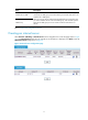
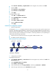
# Configure the FTP server.
• Select Firewall > NAT Policy > Internal Server from the navigation tree, and then click Add in the
Internal Server field.
• Select GigabitEthernet0/2 for Interface.
• Select 6(TCP) for Protocol Type.
• Click the radio button next to Assign IP Address, and then type 202.38.1.1 in Global IP.
• Select the upper radio button next to Global Port and type 21 .
FTP server
10.110.10.3/16
Web server 1
10.110.10.1/16
Web server 2
10.110.10.2/16
SMTP server
10.110.10.4/16
Host
Internet
GE0/1
10.110.10.10/16
GE0/2
202.38.1.1/24
Firewall