
R3166-R3206-HP High-End Firewalls NAT and ALG Configuration Guide-6PW101

22
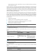
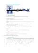
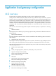
Figure 16 Network diagram for dynamic NAT III
2. Configuration procedure
# As shown in Figure 16, conf
igure the IP addresses for the interfaces (omitted).
# Configure address pool 1.
<Firewall> system-view
[Firewall] nat address-group 1 202.38.1.2 202.38.1.3
# Configure ACL 2001, permitting only users from network segment 10.110.10.0/24 to access the
Internet.
[Firewall] acl number 2001
[Firewall-acl-basic-2001] rule permit source 10.110.10.0 0.0.0.255
[Firewall-acl-basic-2001] rule deny
[Firewall-acl-basic-2001] quit
# Associate address pool 1 and ACL 2001 with the outbound interface GigabitEthernet 0/2.
• No-PAT
[Firewall] interface gigabitethernet 0/2
[Firewall-GigabitEthernet0/2] nat outbound 2001 address-group 1 no-pat
[Firewall-GigabitEthernet0/2] quit
• NAPT
[Firewall] interface gigabitethernet 0/2
[Firewall-GigabitEthernet0/2] nat outbound 2001 address-group 1
[Firewall-GigabitEthernet0/2] quit
Common internal server configuration example
1. Network requirements
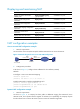
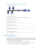
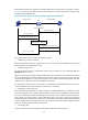
As shown in Figure 17, a c
ompany provides two web servers, one FTP server, and one SMTP server for
external users to access. The internal network address is 10.110.0.0/16. The internal address for the FTP
server is 10.110.10.3/16, for web server 1 is 10.110.10.1/16, for web server 2 is 10.110.10.2/16, and for
the SMTP server 10.110.10.4/16. The company has three public IP addresses ranging from
202.38.1.1/24 to 202.38.1.3/24. Specifically, the company has the following requirements:
• External hosts can access internal servers with public address 202.38.1.1/24.
• Port 8080 is used for web server 2.