
R3166-R3206-HP High-End Firewalls Network Management Configuration Guide-6PW101

96
[Sysname-GigabitEthernet0/1] port inline-interfaces 1
# Assign GigabitEthernet 0/2 to forward-type inline Layer 2 forwarding entry 1.
[Sysname-GigabitEthernet0/1] interface GigabitEthernet 0/2
[Sysname-GigabitEthernet0/2] port inline-interfaces 1
Blackhole-type inline Layer 2 forwarding
configuration example
Network requirements
Configure blackhole-type inline Layer 2 forwarding on GigabitEthernet 0/1. Then packets received on
GigabitEthernet 0/1 are directly dropped.
Configuration procedure
# Create blackhole-type inline Layer 2 forwarding entry 1.
<Sysname> system-view
[Sysname] inline-interfaces 1 blackhole
# Assign GigabitEthernet 0/1 to blackhole-type inline Layer 2 forwarding entry 1.
[Sysname] interface GigabitEthernet 0/1
[Sysname-GigabitEthernet0/1] port inline-interfaces 1
Configuring inter-VLAN Layer 2 forwarding
NOTE:
• For inter-VLAN Layer 2 forwarding confi
g
uration commands, see Interface mana
g
ement confi
g
uration
commands and IP addressing configuration commands in Network Management Command Reference,
and the chapter “VLAN configuration.”
• The firewall supports inter-VLAN Layer 2 forwarding only in the command line interface (CLI).
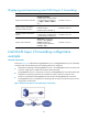
Configuring inter-VLAN Layer 2 forwarding
Perform the following configurations to achieve Layer 2 forwarding between two VLANs.
1. Configure the ports of the switch.
• Create two VLANs. Assign the ingress port of traffic to one VLAN and the egress port to the other.
• Configure the switch’s ten-GigabitEthernet port that connects to the firewall card as a trunk port and
configure the trunk port to join these two VLANs.
2. Configure the firewall card.
• Create three VLANs. Two VLANs have the same IDs with those configured on the switch and the
third one is VLAN X.
• Configure the operating mode of the ten-GigabitEthernet interface that connects to the switch as
Layer 2 mode, and configure the link type of the interface as trunk.
• Create two subinterfaces for the ten-GigabitEthernet interface, and use the IDs of those two VLANs
created on the switch as their interface numbers respectively. Set the link type of the subinterfaces
as access and assign the two subinterfaces to VLAN X.