
R3166-R3206-HP High-End Firewalls Network Management Configuration Guide-6PW101


154
Displaying and maintaining the DHCP client
To do… Use the command…
Remarks
Display specified configuration
information
display dhcp client [ verbose ]
[ interface interface-type
interface-number ]
Available in any view
DHCP client configuration example
Network requirements
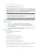
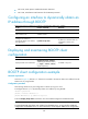
As shown in Figure 78, on a LAN, Firewall contacts the DHCP server via GigabitEthernet 0/1 to obtain
an IP address, DNS server address, and static route information. The IP address resides on network
10.1.1.0/24. The DNS server address is 20.1.1.1. The next hop of the static route to network 20.1.1.0/24
is 10.1.1.2.
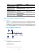
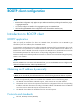
The DHCP server uses Option 121 to assign static route information to DHCP clients. Figure 77 sh
ows the
format of Option 121. The destination descriptor field comprises two parts, subnet mask length and
destination network address. In this example, the value of the destination descriptor field takes 18 14 01
01, a hexadecimal number indicating that the subnet mask length is 24 and destination network address
is 20.1.1.0, and the value of the next hop address field takes 0A 01 01 02, a hexadecimal number
indicating that the next hop is 10.1.1.2.
Figure 77 Option 121 format
Figure 78 Network diagram for DHCP client configuration example
Configuration procedure
1. Configure Router A
# Specify the IP address of GigabitEthernet 1/1.
<RouterA> system-view
[RouterA] interface GigabitEthernet 1/1
[RouterA-GigabitEthernet1/1] ip address 10.1.1.1 24
[RouterA-GigabitEthernet1/1] quit
Firewall
DHCP Client
DNS server
Router A
DHCP server
GE1/1
10.1.1.1/24
GE0/1
Router B
10.1.1.2/24 20.1.1.2/24
20.1.1.1/24