
R3166-R3206-HP High-End Firewalls Network Management Configuration Guide-6PW101


199
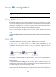
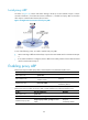
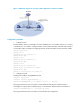
Figure 110 Network diagram for local proxy ARP configuration in isolate-user-VLAN
Configuration procedure
1. Configure Switch
# Create VLAN 2, VLAN 3, and VLAN 5 on Switch. Add Ethernet 1/3 to VLAN 2, Ethernet 1/1 to VLAN
3, and Ethernet 1/2 to VLAN 5. Configure VLAN 5 as the isolate-user-VLAN, and VLAN 2 and VLAN 3
as secondary VLANs. Configure the mappings between isolate-user-VLAN and the secondary VLANs.
<Switch> system-view
[Switch] vlan 2
[Switch-vlan2] port ethernet 1/3
[Switch-vlan2] quit
[Switch] vlan 3
[Switch-vlan3] port ethernet 1/1
[Switch-vlan3] quit
[Switch] vlan 5
[Switch-vlan5] port ethernet 1/2
[Switch-vlan5] isolate-user-vlan enable
[Switch-vlan5] quit
[Switch] isolate-user-vlan 5 secondary 2 3
2. Configure Firewall
# Specify the IP address of GigabitEthernet 0/0.
<Firewall> system-view
[Firewall] interface gigabitethernet 0/0
[Firewall-GigabitEthernet0/0] ip address 192.168.10.100 255.255.0.0
The ping operation from Host A to Host B is unsuccessful because they are isolated at Layer 2.
# Configure local proxy ARP to implement Layer 3 communication between VLAN 2 and VLAN 3.
[Firewall-GigabitEthernet0/0] local-proxy-arp enable
The ping operation from Host A to Host B is successful after the configuration.
Firewall