
R3166-R3206-HP High-End Firewalls Network Management Configuration Guide-6PW101


260
[FirewallA] rip
[FirewallA-rip-1] version 2
[FirewallA-rip-1] undo summary
# Configure RIPv2 on Firewall B.
[FirewallB] rip
[FirewallB-rip-1] version 2
[FirewallB-rip-1] undo summary
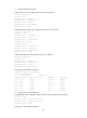
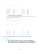
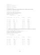
# Display the RIP routing table of Firewall A.
[FirewallA] display rip 1 route
Route Flags: R - RIP, T - TRIP
P - Permanent, A - Aging, S - Suppressed, G - Garbage-collect
--------------------------------------------------------------------------
Peer 1.1.1.2 on GigabitEthernet0/0
Destination/Mask Nexthop Cost Tag Flags Sec
10.0.0.0/8 1.1.1.2 1 0 RA 87
10.1.1.0/24 1.1.1.2 1 0 RA 19
10.2.1.0/24 1.1.1.2 1 0 RA 19
From the routing table, you can see RIPv2 uses classless subnet mask.
NOTE:
Since RIPv1 routing information has a lon
g
a
g
in
g
time, it will still exist before bein
g
a
g
ed out after RIPv2
is configured.
RIP route redistribution configuration example
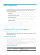
Network requirements
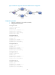
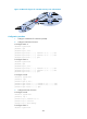
As shown in Figure 145:
• Two RIP processes are running on Firewall, which communicates with Router A through RIP 100 and
with Router B through RIP 200.
• Configure RIP 200 to redistribute direct routes and routes from RIP 100 on Firewall. Thus, Router B
can learn routes destined for 10.1.1.0/24 and 11.1.1.0 / 24, w h i l e R o u t e r A c a n n o t l e a r n ro u t e s
destined for 12.3.1.0/24 and 16.4.1.0/24.
• Configure a filtering policy on Firewall to filter out the route 10.2.1.1/24 from RIP 100, making the
route not advertised to Router B.
Figure 145 Network diagram for RIP route redistribution configuration
Configuration procedure
1. Configure an IP address for each interface (omitted)