
R3166-R3206-HP High-End Firewalls Network Management Configuration Guide-6PW101


279
# Configure Device C.
• Select Network > Routing Management > OSPF from the navigation tree of Device C.
• Select the Enable OSPF check box.
• Select the Import static routes check box.
• Click Apply.
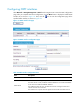
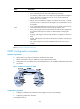
• Click Add on the Area Configuration tab.
• Type 1 for Area ID.
• Select NSSA for Area Type.
• Type 10.2.1.0 for Network Address, and select 0.0.0.255 for Network Mask. Then, click Add
Network.
• Type 10.4.1.0 for Network Address, and select 0.0.0.255 for Network Mask. Then, click Add
Network.
• Click Apply.
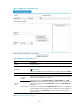
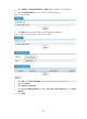
• Select Network > Static Route from the navigation tree and click Add.
• Type 3.2.1.1 as the destination IP address.
• Select 255.255.255.0 from the mask drop-down list.
• Type 10.4.1.2 a
s the next hop.
• Click Apply.
# Configure Device D.
• Select Network > Routing Management > OSPF from the navigation tree of Device D.
• Select the Enable OSPF check box.
• Click Apply.
• Click Add on the Area Configuration tab.
• Type 2 for Area ID.
• Select Normal for Area Type.
• Type 10.3.1.0 for Network Address, and select 0.0.0.255 for Network Mask. Then, click Add
Network.
• Type 10.5.1.0 for Network Address, and select 0.0.0.255 for Network Mask. Then, click Add
Network.
• Click Apply.
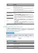
Verify the configuration
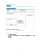
# Display neighbor information of Device A.
Select Network > Routing Management > OSPF from the navigation tree of Device A, and then click
Show Peer in the Show Information field. A neighbor in Full state is displayed in area 0 and area 1
respectively, as shown in Figure 160.
(192.168.1.42 is the router ID of Device B, and 192.168.1.57 is the
router ID of Device C.)
Figure 160 OSPF configuration result I