
R3166-R3206-HP High-End Firewalls Network Management Configuration Guide-6PW101


316
IP Address Type State Cost Pri DR BDR
192.168.1.1 Broadcast DR 1 100 192.168.1.1 192.168.1.3
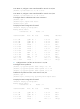
[RouterB] display ospf interface
OSPF Process 1 with Router ID 2.2.2.2
Interfaces
Area: 0.0.0.0
IP Address Type State Cost Pri DR BDR
192.168.1.2 Broadcast DROther 1 0 192.168.1.1 192.168.1.3
NOTE:
The interface state
DROther
means the interface is not the DR/BDR.
OSPF virtual link configuration example
Network requirements
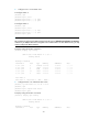
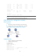
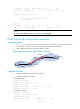
• In Figure 168, Area 2 has no direct connection to Area 0, and Area 1 acts as the Transit Area to
connect Area 2 to Area 0 via a virtual link between Firewall A and Firewall B.
• After configuration, Firewall A can learn routes to Area 2.
Figure 168 Network diagram for OSPF virtual link configuration
Configuration procedure
1. Configure IP addresses for interfaces (omitted).
2. Configure OSPF basic functions.
# Configure Router A.
<RouterA> system-view
[RouterA] ospf 1 router-id 1.1.1.1
[RouterA-ospf-1] area 0
[RouterA-ospf-1-area-0.0.0.0] network 10.1.1.0 0.0.0.255
[RouterA-ospf-1-area-0.0.0.0] quit
# Configure Firewall A.
<FirewallA> system-view
[FirewallA] ospf 1 router-id 2.2.2.2
[FirewallA-ospf-1] area 0
[FirewallA-ospf-1-area-0.0.0.0] network 10.1.1.0 0.0.0.255
Area 0
Router A
Eth1/1
10.1.1.1/24
Firewall A
Area 2
GE0/0
10.1.1.2/24
GE0/1
10.3.1.2/24
Eth1/1
10.3.1.1/24
V
i
r
t
u
a
l
l
i
n
k
GE0/1
10.2.1.1/24
GE0/0
10.2.1.2/24
Area 1
Firewall B
Router B