
R3166-R3206-HP High-End Firewalls Network Management Configuration Guide-6PW101


390
[Firewall-GigabitEthernet0/2] ip address 1.1.3.1 255.255.255.0
b. Configure Router A
# Configure a static route to subnet 10.110.0.0/24.
<RouterA> system-view
[RouterA] ip route-static 10.110.0.0 24 1.1.2.1
# Configure the IP address of the serial port.
[RouterA] interface GigabitEthernet 0/1
[RouterA-GigabitEthernet0/1] ip address 1.1.2.2 255.255.255.0
[RouterA-GigabitEthernet0/1] quit
c. Configure Router B
# Configure a static route to subnet 10.110.0.0/24.
<RouterB> system-view
[RouterB] ip route-static 10.110.0.0 24 1.1.3.1
# Configure the IP address of the serial port.
[RouterB] interface GigabitEthernet 0/1
[RouterB-GigabitEthernet0/1] ip address 1.1.3.2 255.255.255.0
[RouterB-GigabitEthernet0/1] quit
3. Verification
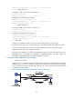
Configure the IP address of Host A as 10.110.0.20/24, and the gateway as 10.110.0.10.
On Host A, telnet to Router A (1.1.2.2) that is directly connected to Firewall. The operation succeeds.
On Host A, telnet to Router B (1.1.3.2) that is directly connected to Firewall. The operation fails.
Ping Router B from Host A. The operation succeeds.
Telnet uses TCP, and ping uses ICMP. The preceding results show that all TCP packets arriving on
GigabitEthernet0/1 of Firewall are forwarded via GigabitEthernet0/3, and other packets are
forwarded via GigabitEthernet0/2. The PBR configuration is effective.
Configuring interface PBR based on packet length
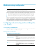
1. Network requirements
As shown in Figure 198, PBR is conf
igured to control packets arriving on GigabitEthernet0/3 of Firewall.
Configure 150.1.1.2/24 as the next hop for packets with a length of 64 to 100 bytes, and configure
151.1.1.2/24 as the next hop for packets with a length of 101 to 1000. All other packets are forwarded
according to the routing table.
Figure 198 Network diagram for interface PBR based on packet length