
R3166-R3206-HP High-End Firewalls Network Management Configuration Guide-6PW101


404
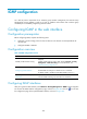
Network diagram
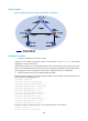
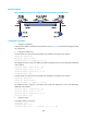
Figure 204 Network diagram for configuring multicast forwarding over a GRE tunnel
Configuration procedure
1. Configure IP addresses
Configure the IP address and mask for each interface as per Figure 204. T
he detailed configuration steps
are omitted here.
2. Configure a GRE tunnel
# Create Tunnel 0 on Firewall A and configure the IP address and mask for the interface.
<FirewallA> system-view
[FirewallA] interface tunnel 0
[FirewallA-Tunnel0] ip address 50.1.1.1 24
# Configure Tunnel 0 to work in the GRE tunnel mode and specify the source and destination addresses
of the interface.
[FirewallA-Tunnel0] tunnel-protocol gre
[FirewallA-Tunnel0] source 20.1.1.1
[FirewallA-Tunnel0] destination 30.1.1.2
[FirewallA-Tunnel0] quit
# Create Tunnel 0 on Firewall C and configure the IP address and mask for the interface.
<FirewallC> system-view
[FirewallC] interface tunnel 0
[FirewallC-Tunnel0] ip address 50.1.1.2 24
# Configure Tunnel to operate in the GRE tunnel mode and configure the source and destination
addresses of the interface.
[FirewallC-Tunnel0] tunnel-protocol gre
[FirewallC-Tunnel0] source 30.1.1.2
[FirewallC-Tunnel0] destination 20.1.1.1
[FirewallC-Tunnel0] quit
3. Configure OSPF.
# Configure OSPF on Firewall A.
[FirewallA] ospf 1
[FirewallA-ospf-1] area 0
[FirewallA-ospf-1-area-0.0.0.0] network 10.1.1.0 0.0.0.255