
R3166-R3206-HP High-End Firewalls Network Management Configuration Guide-6PW101

34
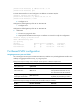
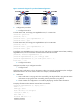
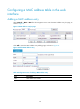
Figure 19 Network diagram for port-based VLAN configuration
2. Configuration procedure
a. Configure Firewall A
# Create VLAN 100, and assign port GigabitEthernet 0/1 to VLAN 100.
<FirewallA> system-view
[FirewallA] vlan 100
[FirewallA-vlan100] port GigabitEthernet 0/1
[FirewallA-vlan100] quit
# Create VLAN 200, and assign port GigabitEthernet 0/2 to VLAN 200.
[FirewallA] vlan 200
[FirewallA-vlan200] port GigabitEthernet 0/2
[FirewallA-vlan200] quit
# Configure port GigabitEthernet 0/3 as a trunk port, and assign it to VLANs 100 and 200, enabling
GigabitEthernet 0/3 to forward traffic of VLANs 100 and 200 to Firewall B.
[FirewallA] interface GigabitEthernet 0/3
[FirewallA-GigabitEthernet0/3] port link-type trunk
[FirewallA-GigabitEthernet0/3] port trunk permit vlan 100 200
Please wait... Done.
b. Configure Firewall B
Configure Firewall B as you configure Firewall A.
c. Configure hosts
Configure Host A and Host C to be on the same IP subnet. For example, 192.168.100.0/24. Configure
Host B and Host D to be on the same IP subnet. For example, 192.168.200.0/24.
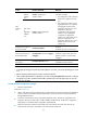
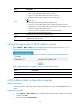
3. Verification
a. Host A and Host C can ping each other successfully, but they both fail to ping Host B. Host B
and Host D can ping each other successfully, but they both fail to ping Host A.
b. Check whether the configuration is successful by displaying relevant VLAN information.
# Display information about VLANs 100 and 200 on Firewall A.
[FirewallA-GigabitEthernet0/3] display vlan 100
VLAN ID: 100
VLAN Type: static
Route Interface: not configured
Description: VLAN 0100
Name: VLAN 0100
Broadcast MAX-ratio: 100%
Tagged Ports: