
R3166-R3206-HP High-End Firewalls Network Management Configuration Guide-6PW101

465
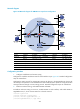
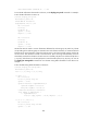
Network diagram
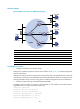
Figure 227 Network diagram for PIM-SM non-scoped zone configuration
Device Interface IP address
Device
Interface IP address
Device A GE0/1 10.110.1.1/24
Firewall D
GE0/0
10.110.5.1/24
GE0/0 192.168.1.1/24
GE0/1 192.168.1.2/24
GE0/2 192.168.9.1/24
GE0/2
192.168.4.2/24
Device B GE0/1 10.110.2.1/24
Firewall E
GE0/0
192.168.3.2/24
GE0/0 192.168.2.1/24
GE0/1 192.168.2.2/24
Device C GE0/1 10.110.2.2/24
GE0/2
192.168.9.2/24
GE0/0 192.168.3.1/24
GE0/3
192.168.4.1/24
Configuration procedure
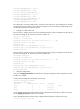
1. Configure IP addresses and unicast routing
Configure the IP address and subnet mask for each interface as per Figure 227.
Detailed configuration
steps are omitted here.
Configure the OSPF protocol for interoperation among the devices in the PIM-SM domain. Ensure the
network-layer interoperation in the PIM-SM domain and enable dynamic update of routing information
among the devices through a unicast routing protocol. Detailed configuration steps are omitted here.
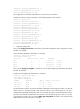
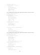
2. Enable IP multicast routing, and enable PIM-SM and IGMP
# Enable IP multicast routing on Device A, enable PIM-SM on each interface, and enable IGMP on
GigabitEthernet 0/1, which connects Device A to the stub network.
<DeviceA> system-view
[DeviceA] multicast routing-enable
[DeviceA] interface gigabitEthernet 0/1
[DeviceA-GigabitEthernet0/1] igmp enable
Ethernet
EthernetEthernet
N1N2
G
E0
/
3
G
E
0
/
3