
R3166-R3206-HP High-End Firewalls Network Management Configuration Guide-6PW101


491
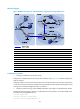
Network diagram
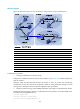
Figure 230 Network diagram for inter-AS multicast configuration leveraging BGP routes
Device Interface IP address Device Interface IP address
Device
A
GE0/1 10.110.1.2/24
Device
D
GE0/1
10.110.4.2/24
GE0/2 10.110.2.1/24
GE0/2
10.110.5.1/24
GE0/3 10.110.3.1/24 Firewall E GE0/1 10.110.6.1/24
Firewall B GE0/1 10.110.1.1/24
GE0/3
192.168.3.2/24
GE0/0 192.168.1.1/24
Loop0
3.3.3.3/32
Loop0 1.1.1.1/32 Device F GE0/1 10.110.6.2/24
Firewall C GE0/1 10.110.4.1/24
GE0/2
10.110.7.1/24
GE0/3 192.168.3.1/24
Source 1
—
10.110.2.100/24
GE0/0 192.168.1.2/24 Source 2 — 10.110.5.100/24
Loop0 2.2.2.2/32
Configuration procedure
1. Configure IP addresses and unicast routing
Configure the IP address and subnet mask for each interface as per Figure 230.
Detailed configuration
steps are omitted.
Configure OSPF for interconnection between devices in each AS. Ensure the network-layer interoperation
in each AS, and ensure the dynamic update of routing information between the devices through a unicast
routing protocol. Detailed configuration steps are omitted.
2. Enable IP multicast routing, enable PIM-SM and IGMP, and configure a PIM-SM domain border
# Enable IP multicast routing on Device A, enable PIM-SM on each interface, and enable IGMP on the
host-side interface GigabitEthernet 0/3.
<DeviceA> system-view
[DeviceA] multicast routing-enable
[DeviceA] interface gigabitEthernet 0/1