
R3166-R3206-HP High-End Firewalls Network Management Configuration Guide-6PW101

504
• Set up an MSDP peering relationship between Firewall A and Firewall C and between Firewall C
and Firewall D.
• S o u r c e 1 s e n d s m u l t ic a s t d a t a t o m u l t i c a s t g rou p s 225.1.1.0 / 3 0 a n d 226.1.1.0 / 30 , a n d S o u rc e 2
sends multicast data to multicast group 227.1.1.0/30.
• Configure SA message filtering rules so that receivers Host A and Host B can receive only the
multicast data addressed to multicast groups 225.1.1.0/30 and 226.1.1.0/30, while Host can
receive only the multicast data addressed to multicast groups 226.1.1.0/30 and 227.1.1.0/30.
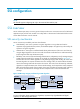
Network diagram
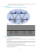
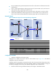
Figure 233 Network diagram for SA message filtering configuration
Device Interface IP address Device Interface IP address
Source 1 — 10.110.3.100/24
Firewall C
GE0/0
10.110.4.1/24
Source 2 — 10.110.6.100/24
GE0/3
10.110.5.1/24
Firewall A GE0/0 10.110.1.1/24 GE0/1 192.168.1.2/24
GE0/3 10.110.2.1/24
GE0/2
192.168.2.2/24
GE0/1 192.168.1.1/24
Loop0
2.2.2.2/32
Loop0 1.1.1.1/32 Firewall D GE0/0 10.110.6.1/24
Device B GE0/0 10.110.3.1/24
GE0/1
10.110.7.1/24
GE0/3 10.110.2.2/24
GE0/3
10.110.5.2/24
GE0/1 192.168.2.1/24 Loop0 3.3.3.3/32
Configuration Procedure
1. Configure IP addresses and unicast routing
Configure the IP address and subnet mask for each interface as per Figure 233. T
he detailed
configuration steps are omitted here.
Configure OSPF for interoperation among the firewalls. Ensure the network-layer interoperation within
and between the PIM-SM domains and ensure dynamic update of routing information among the
firewalls by leveraging unicast routing. The detailed configuration steps are omitted here.
2. Enable IP multicast routing, PIM-SM and IGMP, and configure a PIM domain border
MSDP peers
PIM-SM 1PIM-SM 2PIM-SM 3
Loop0
Loop0
Loop0
Source 1
Source 2
Receiver
Host B
Receiver
Host C
Receiver
Host A
GE0/0
GE0/0
GE0/0 GE0/1
GE0/3
GE0/3
G
E
0
/
1
G
E
0
/
1
G
E
0
/
1
G
E
0
/
2
GE0/3
GE0/3
GE0/0
Firewall A
Firewall C
Firewall D
Device B