
R3166-R3206-HP High-End Firewalls Network Management Configuration Guide-6PW101


86
To do... Use the command...
Remarks
Display the root bridge
information of all MSTIs
display stp root Available in any view
Clear the spanning tree
statistics
reset stp [ interface interface-list ] Available in user view
MSTP configuration example
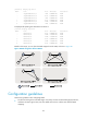
Network requirements
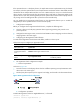
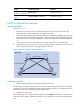
As shown in Figure 39:
• All devices on the network are in the same MST region. Device A and Device B work at the
distribution layer. Firewall and Device C work at the access layer.
• Configure MSTP so that packets of different VLANs are forwarded along different spanning trees:
Packets of VLAN 10 are forwarded along MSTI 1, those of VLAN 30 are forwarded along MSTI 3,
those of VLAN 40 are forwarded along MSTI 4, and those of VLAN 20 are forwarded along MSTI
0.
• VLAN 10 and VLAN 30 are terminated on the distribution layer devices, and VLAN 40 is
terminated on the access layer devices, so the root bridges of MSTI 1 and MSTI 3 are Device A and
Device B respectively, and the root bridge of MSTI 4 is Firewall.
Figure 39 Network diagram for MSTP configuration
Configuration procedure
1. VLAN and VLAN member port configuration (details not shown)
Create VLAN 10, VLAN 20, and VLAN 30 on Device A and Device B respectively, VLAN 10, VLAN 20,
and VLAN 40 on Firewall, and VLAN 20, VLAN 30, and VLAN 40 on Device C. Configure the ports on
these devices as trunk ports and assign them to related VLANs.
2. Configuration on Device A
# Enter MST region view, configure the MST region name as example, map VLAN 10, VLAN 30, and
VLAN 40 to MSTI 1, MSTI 3, and MSTI 4 respectively, and configure the revision level of the MST region
as 0.
Permit: all VLANs
P
e
r
m
i
t:
V
L
A
N
s
2
0
,
3
0
P
e
r
mi
t
:
V
L
A
N
s
1
0
,
2
0
Permit: VLANs 20 , 40
Permit: VLANs 20 ,30Permit: VLANs 10 , 20
Device A Device B
Firewall Device C
GE0/3
G
E
0
/
2
Eth1/3
E
t
h
1
/
2
Eth1/3 Eth1/3
E
t
h
1
/
2
E
t
h
1
/
2
MST region